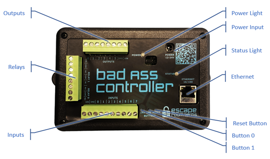
Overview
Game specific wiring diagrams can be found within each game doc.
Inputs Header
The BAC provides 8 digital inputs, the last two of which also double as analog inputs. The number of inputs required and used depends on the game configuration. Most games can be configured to leave at least one input free, which can be used as a Reset or Enable input if needed.
This is how you wire an input pin:

Outputs Header
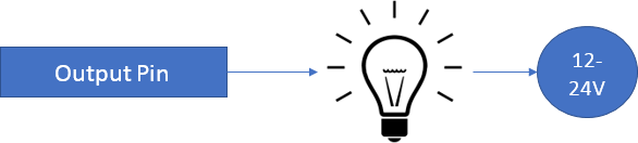
The BAC provides 6 current sinking outputs. When switched closed, the output pin is connected internally to ground, NOT to a voltage source. Each output can sink a max of 500mA of current (6W at 12V or 12W at 24V). Total combined limit for all outputs is 2500mA. The number of outputs required and used depends on the game configuration. Most games can be configured to leave at least one output free, which can be used as a Solve output if needed. Additionally, the relays can be used as outputs, typically a solve output.
This is how you wire an output pin:
Relays Header
There are 2 relay outputs suitable for higher current devices like motors or larger maglocks. The configuration of the relays is game dependent. Each relay can handle 10A each. In most cases, they will switch 12V or 24V. This is acceptable with the standard, exposed case. In cases where a qualified user wishes to switch 110V AC, the relays are suitable for this application and Escape Room Techs recommends using a DIN rack mounting kit in a proper wiring cabinet or the dedicated enclosure which is a proper, small wiring cabinet for such applications. Consult Escape Room Techs if you have further questions.
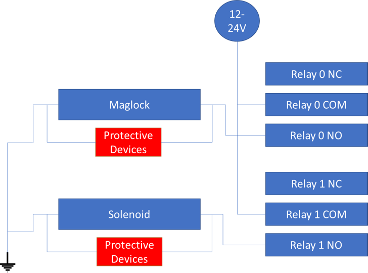
The relay header supports 2 Form-C relays. Form-C means they have a common (COM), normally open (NO), and a normally closed (NC). Relays are not typically part of the game logic and are typically used for the final solve action to power a maglock, solenoid, linear actuator, or large LED. Large outputs devices like motors, linear actuators, large maglocks, LEDs, etc., anything over 1A or inductive or noisy, should have a separate power supply. Be aware that large inducive loads (anything that uses magnetism like motors and maglocks) create electrical noise and back EMF. While the BAC is built with industrial I/O protection, it cannot protect against everything in all situations, as it is unknown exactly how the end user will use the device. It is the responsibility of the user to protect against these types of interferences. Typically, this involves diodes, MOVs, and capacitors. Please consult Escape Room Techs if you have issues with stability or resets.
This is how you wire a relay to control a maglock or solenoid:
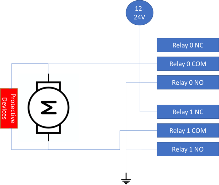
Alternatively, a linear actuator can be wired like this (the kind that turn themselves off at the limits automatically):
Power LED
Red LED. Stays solid when BAC is supplied with +12 to +24VDC
Power Input
Provide +12 - 24VDC to the BAC using either a power supply with a 5.5mm x 2.1mm center positive barrel connector, or by wiring directly into any of the I/O headers at VIN/GND or +/-.
The BAC may also supply power via the I/O headers. Ensure that the power supply you use is capable of providing enough current for the BAC and any devices powered from it. The BAC itself uses very little current and draws about 50mA at 12V / 25mA at 24V.
Status LED
"Breathes" on bootup. After boot will flash once for successful DHCP request or three times for DHCP fail (DHCP mode only). After will continue to blink on every second. When game is solved will blink off every second.
Fast Ethernet
Connect one end of an RJ-45 Ethernet cable to the Ethernet port of the BAC and the other to your router / switch. Future versions of BAM will include a built-in DHCP server, allowing you to connect your BAC directly to the Ethernet port on your computer without the need for additional networking hardware.
Reset Button
Resets the BAC.
Input 0 Button
Tied to the input 0 pin on the inputs header. Pressing this button is the same as connecting input 0 to VIN. This input can also be used to clear user settings on startup.
Input 1 Button
Tied to the input 1 pin on the inputs header. Pressing this button is the same as connecting input 1 to VIN.