Overview
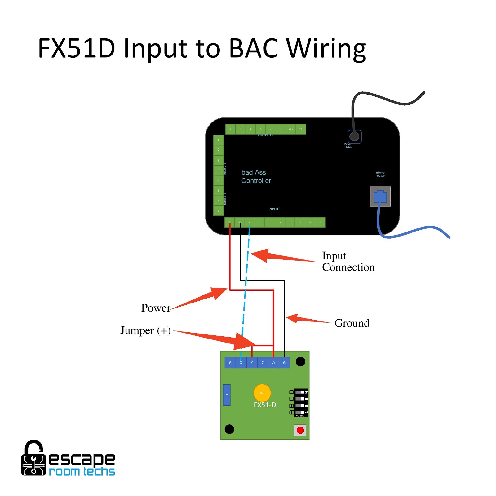
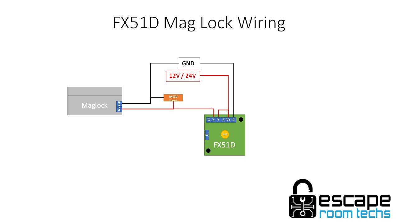
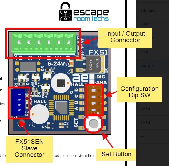
The FX51D is a multifunctional sensing device designed to replace a traditional reed switch but with additional capability. As such the FX51D functions as an input that senses a magnetic field used with any controller such as our Bad Ass Controller (BAC). While the FX51D serves as a sensor, it also provides independent controller functionality. Its built in controller functionality provides for a configurable output and/or can act as a master for other FX51 secondary sensors (FX51SEN).As a magnetic field sensor, the FX51D functionally is capable of detecting four magnetic fields states including rotational position (Rotational), magnet pole detection (Bipolar & Unipolar) and strength/distance (Gated). Used in conjunction as a BAC input, the FX51D can be used to trigger events and outputs in a prop, game, puzzle or in room controller mode. Used as a controller, the FX51D provides a configurable output capable of driving the likes of a low amp maglock, an input to another device and more. Controller mode is also capable of being the master to as many as 8 FX51SEN secondary magnetic field sensors creating a sensor array.
Note: The FX51D sensor and output configurations are toggled through switch A of the dip switch. When configuring the FX51D, first set the sensing mode; switch A is in the down position for this function. Once the sensing mode has been configured and set, change switch A to the up position for setting the output modes if required. See below for additional information on switch settings.
Sensor mode Setup
Create a default baseline calibration / device reset – Set all the dip switches to the off (down) position, removing any nearby magnets, power on the FX51D and press the red “set” button. The status light will flash once and turn on. Note: This also resets the FX51D back to default Bipolar mode.
- Bipolar Mode senses any magnet – This is the default and calibration mode (see above)
- Unipolar Mode senses specific magnetic poles – Set the FX51D switches to down-down-up-down (0010) and press set. It will only trigger with either a North pole or South pole magnetic field. To toggle between north and south pole sensing, press the set button again. When the correct magnetic pole is sensed, the sense status light will turn on. If the wrong pole is sensed, the sense light will continuously flicker.
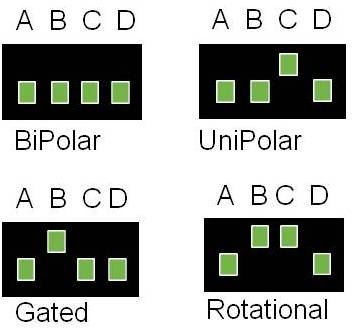
Sensing Mode Dip Switch Settings - Gated Mode senses magnetic strength – Set the FX51D switches to down-up-down-down (0100) and press set. It will only trigger when this magnet is positioned at this distance from the sensor and has the correct North/South pole orientation. Note: For the FX51D to be accurate and function properly, the sensor andmagnets should be installed in their final positions before calibration. Once the sensor and magnet have been installed correctly, position the prop with the magnet/prop over the sensor to calibrate.
- Rotational Mode senses magnetic rotational position – Set the FX51D switches to down-up-up-down (0110) positions, turn the knob/shaft to the solve position and press the red set button; the STAT light will blink. As the knob/shaft is rotated, the SENSE light will turn on when in the solve position. Note: The FX51D requires a rotational magnet positioned against the sensor on the board. As the magnet is rotated the FX51D sensor measures the changes. Our “Indestructible Knob” is preconfigured to specifically work with the FX51D.
Output Mode Setup
The FX51D includes 6 programmable output modes, the most common toggle between normally closed or open when the sensor is in a “solved” state. To enter the output mode, the A dip switch must be up.
1. Normally closed, open when triggered (Default output mode) – To open a maglock (2A), set the dip switches to up-down-down-down (1000) and press the set button
2. Normally open, closed when triggered – To set as an input trigger to another device such as a BAC, PLC or PicoBoo, set the dip switches to up-down-down-up (1001) and press the set button
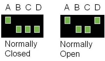
Output Mode Dip Switch Settings
Important Notes
- Dip sw down is in the off position or 0, dip sw up is in the on position or 1
- Magnets should be between ½” & 1.25” away from the sensor for positional detection
- Status light will blink and stay on when powered up
- Switch “A” changes the board from programming the “sense” mode when the switch is down (off) to programming the “output” mode when the switch is up (on)
Specifications
Controller Specifications
| Input voltage | 6 – 26V |
| Outputs | 1 Solid State Relay, 24V (max), 2A |
| Hall Sensor | Digital |
| Processor | NXP/Freescale ARM Cortex M0+ |
Magnetic Specifications
| Gauss Sensitivity | +/- 430 Gauss | |
| Sample Magnet A,.125”x.125”, N42 | 20G from .5” from surface. | D22 |
| Sample Magnet B,.25”x.25”, N42 | 107G from .5” from surface. | D44 |
| Sample Magnet C,. 375”x.50”, N42 | 62G from 1.0” from surface.307G from .5” from surface. | D68 |
| Sample Magnet D,.5”x.5”, N52 | 69G from 1.75” from surface.236G from 1.25” from surface. | D88-N52 |
| When using the same magnet in two positions, the goal is to stay within the sensitivity range but provide enough ‘margin on each side for accurate detection and discretion (difference between the two). When combined with utilizing both poles, 4 or more combinations can be accurately detected. | ||
| Magnetic field calculator and magnets available at https://www.kjmagnetics.com/ |
Additional Information
For additional configuration settings and technical information, see our FX51D Manual
