About
This larger magnetic lock is ideal for keeping full-size doors closed until players have solved a puzzle. Powered by 12V, the lock retains the armature plate as long as power is applied, and the lock is released when power is removed.
Our high-quality locks are manufactured by a trusted partner to our exacting standards, and feature an internal protection diode that helps protect other circuits from electromagnetic interference caused by the lock switching on and off.
We include detailed installation instructions, all necessary mounting hardware, and a helpful template for drilling holes in your door frame or prop.
This lock’s electrical connection is made using a convenient set of screw terminals located behind an access panel or via lever lock connectors, depending on lock model – no wire splicing required!
Like many door sized locks, this product also includes an LED indicator light. We find this feature helpful for troubleshooting while setting up your room, but if you prefer to hide the LED indicator for thematic reasons, it can easily be removed from its mounting hole and stored inside the access panel.
Installation Instructions
- Prepare your mounting location. You’ll want to run power and ground wires between the door lock and your BAC controller before beginning installation, as these wires will be threaded through the lock body during the installation. Make sure to use wire thick enough to accommodate the current requirements of this lock at 0.5A – we recommend at least 20 AWG, with 18 AWG preferred. If you are using a multi-conductor cable with lower gauge, you can potentially double-up two conductors for positive and two conductors for negative; refer to an ampacity calculator for details.
-
Identify which revision of our magnetic lock you have. If your lock came with external lever lock connectors and an attached pigtail, you’ll make the connection outside the lock. If your lock doesn’t have an attached pigtail, connections are made by removing the front access panel and threading the wire into a screw terminal inside.
- Orient yourself with the lock. The lock consists of three parts:
Lock Body – this is the portion of the lock which is powered by the controller and which generates the magnetic field to hold the door closed. It is typically mounted inside your doorframe.
Mounting Plate – this ships attached to the lock body by four hex screws captive within the holes at the edges of the lock body. To mount the lock, you will remove this plate, screw it to your doorframe, and then reinstall the lock once it is in the correct position.
Armature Plate – this is a thick, heavy metal slug that fastens through your door via a large bolt in the center. It should be aligned such that it can mate flush with the lock body once installed.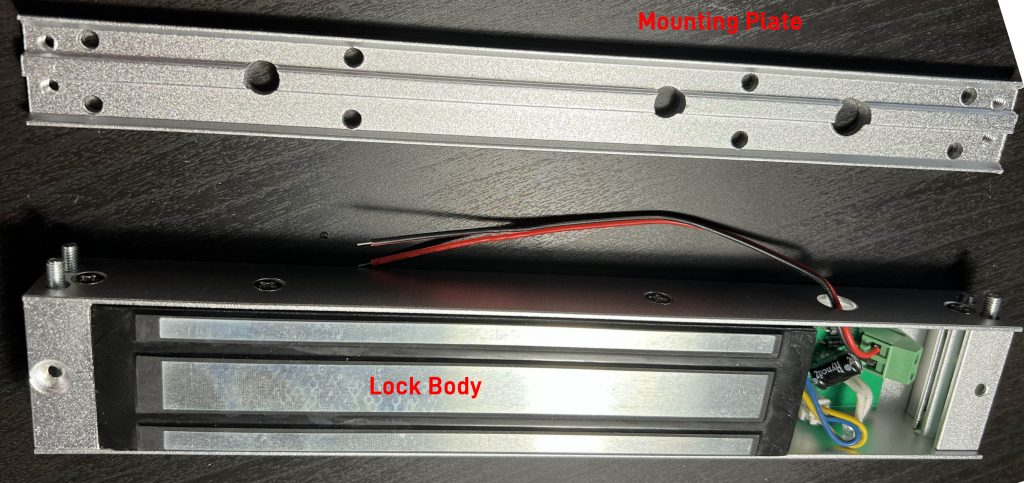
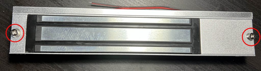
- Remove the mounting plate from the lock body.
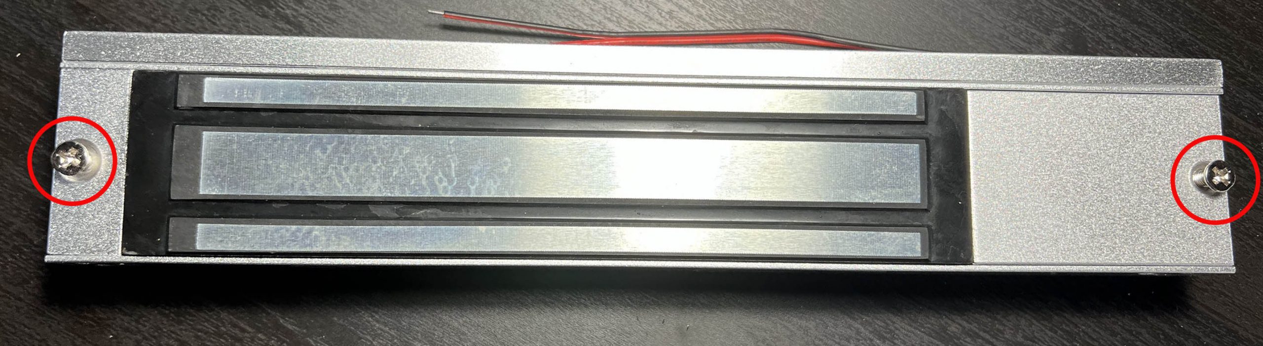
- First, remove the two Phillips head screws from the front of the lock if present; these screws may prevent access to the four hex screws securing the mounting plate.
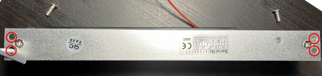
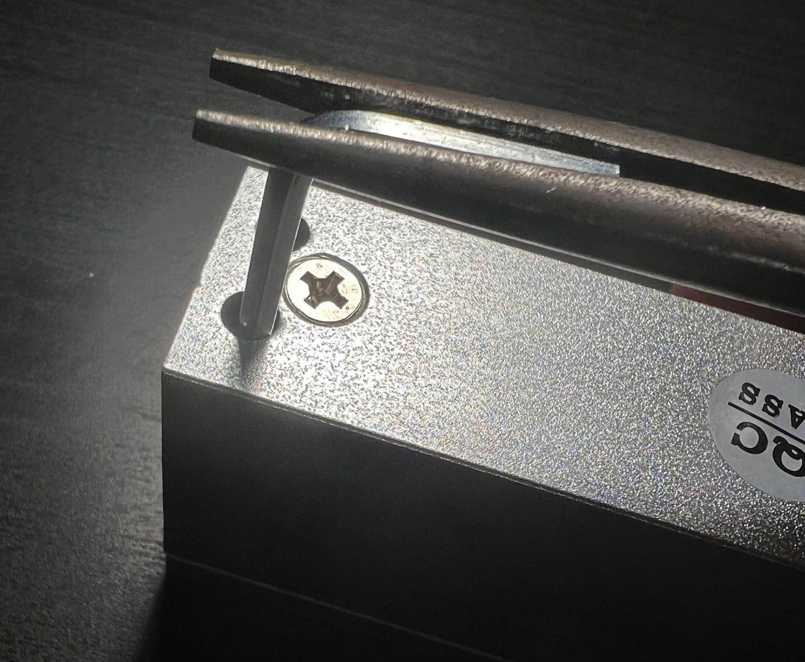
- Second, remove the four hex screws from the lock body using the supplied hex wrench.
These screws may be quite tight, so you may find it helpful to use pliers to gain extra leverage as shown.
This will free the upper lock body.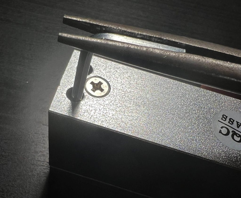
- First, remove the two Phillips head screws from the front of the lock if present; these screws may prevent access to the four hex screws securing the mounting plate.
- Mark locations and drill starter holes for the screws that will retain the lock using the upper mounting plate you just removed. (You can also use our mounting template if you prefer, but we suggest using the lock body itself for the large locks as the aluminum holes are very easy to trace inside of.)
- Drill an additional hole for the wiring.
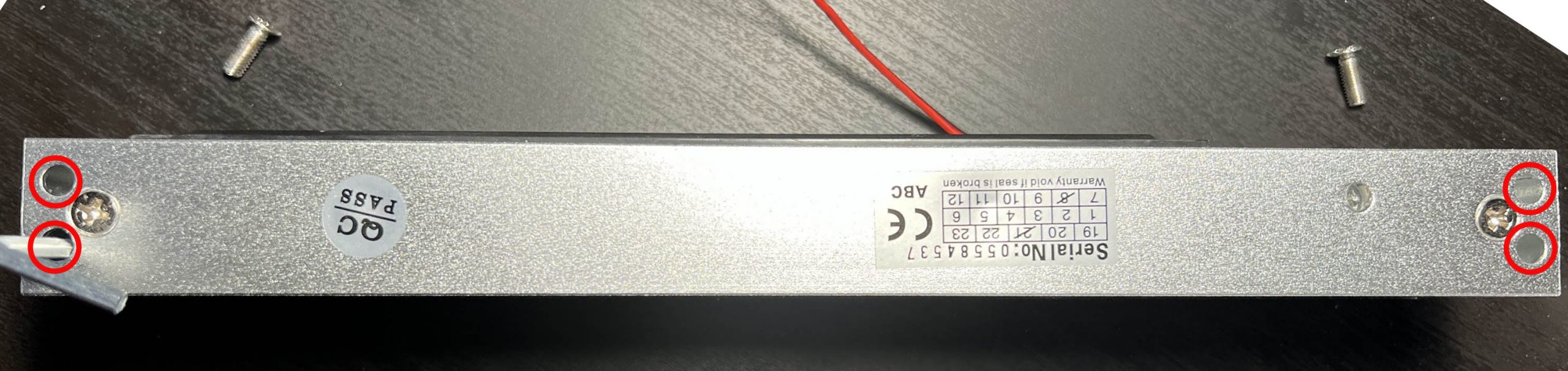
- Thread the wiring through the mounting plate, then secure the mounting plate to your doorframe with screws. There are eight possible screw holes in the channels of the mounting plate; use as many as you deem necessary. (Do not use the two larger holes, as a screw head in them will prevent the lock body from mounting.)
- Thread the wiring through the lock body into the lock wiring compartment, then mount the lock body onto the mounting plate. Secure with the four hex-head screws.
(If using the pigtail, thread the pigtail up through the door into a maintenance area instead before securing the lock.
- Make the connections to the lock.
Internal Connection: If you have a version with screw terminals inside the lock, thread the wire in and secure it as shown: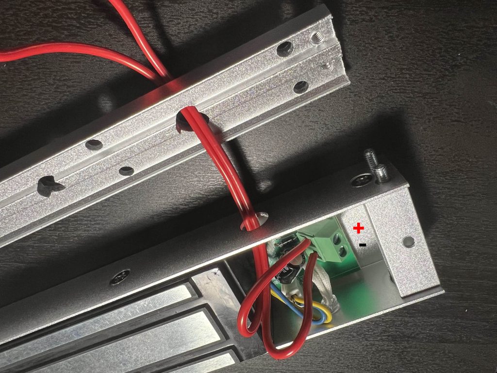
If connecting internally: Unscrew the positive and negative terminals of the lock, then connect your wiring to these terminals and secure with a flathead screwdriver. The terminal closest to the top entry hole should be + and the one closest to the bottom LED light is -.
External connections: Thread the pigtail to a maintenance area, then make connections using the lever lock wire connectors supplied. For straight-through 2×2 lever locks, connect the positive/red wires to the orange levers, and connect the negative/black wires to the blue levers. For single 1×2 lever locks, connect the positive/red wires with one lever lock device, and connect the negative/black wires with the other lever lock device.
In both cases: Consider using ferrules to ensure firm, reliable connections to your wires. If not using ferrules, strip wire to the correct length; for screw terminals, strip about 6mm of bare copper, and for lever lock wires, strip about 11mm of bare copper. (Lever locks should have a small length guide molded into or printed on the plastic to help with this.) - Test the lock. Apply power to the lock, then place the armature plate on the lock and make sure it secures firmly. Be very, very careful when removing power – have someone nearby and coordinate to catch the slug as it falls to avoid damaging your flooring, or someone’s head or toes.
(Speaking from experience, you definitely don’t want to clonk yourself with one of these heavy plates!)
- Decide if you want the LED light to indicate when the door is locked or not. This can be helpful during reset, but may be distracting if the lock body is visible to players while gameplay is active. If you do not want the LED, simply pop it out of its hole behind the access panel and tuck it inside the lock body out of view. You can also mask the LED with a piece of electrical tape if needed.
- Mount the armature plate. If you’re confident in your alignment skills, you can simply drill holes using the plate as a mounting template, install the armature plate, and test it. However, we find that often woodworking is imperfect and it can be difficult to achieve perfect alignment.
While one approach is to slightly loosen the plate so it has enough ‘give’ to latch properly, that can rattle around and make locks tempting for players to tamper with. Another trick we’ve developed over the years may help allow you to make a secure installation:
- Turn on the lock body and mount the armature plate, smooth side facing the lock body.
- Warm up a large hot glue gun for a longer-than-usual amount of time, ensuring the glue stays molten for a while after it is dispensed.
- Dispense a generous blob of glue to the back of the armature plate. Do not cover the mounting hole. Be very careful to not burn yourself and consider wearing gloves for safety, as molten hot melt glue can linger and cause serious injury.
- Close your door, and allow the glue to cool so the armature plate is now glued to the door, creating a custom shim that is exactly aligned for your installation.
- Turn off power to the lock, and open the door again.
- Drill a hole through the center of the armature plate, then mount the hardware as normal.
- Secure the front cover with the two screws you removed in Step 1. You’re done!


Specifications
Lock body: 250mm x 47mm x 25mm
Armature plate: 190mm x 45mm x 11mm
Holding force: 280kg / 600lbs
Current consumption: 520mA
Voltage: 12V
Weight: 2.1kgs
Certification: CE