Introduction
Designed for the modern escape room professional, the Bad ASS Controller (BAC) controls puzzles, games, or props without the daunting task of programming. A user selectable option sets the BAC’s basic profile, while dropdown menus via a graphical user interface software called the “Bad ASS Manager” (BAM) provides a simple menu of choices for specific event actions. Protected onboard circuits [Eight (8) inputs, six (6) outputs, two (2) 10 A relays] simplify the wiring structure for sensors, readers, switches, lights, locks, motors and much more. Once configured, puzzle/prop inputs and outputs (I/O) can be optionally monitored and controlled remotely. In the event of a system failure, the BAC can be replaced by a non-technical person in minutes minimizing downtime and revenue loss.
What’s New
BAC V - New name for a new product! - Escape Room Techs has upgraded the “Bad ASS” Controller with some “Bad ASS” changes! Of course, we have! Due to the significance of the new upgrades, the “Bad ASS” Controller has been rebranded the BAC V. “Bad ASS V” on the cover, even more “Bad ASS” on the inside...
Input Upgrades
- Inputs (0-3) have been upgraded to “Opto-Inputs” on the new BAC V to provide increased user flexibility and robustness. The opto isolated inputs can be set to three different configurations:
- Apply DC voltage from the BAC V + terminal to the inputs (original & default mode of all inputs 0-7) to trigger the input.
- Ground the input terminal to trigger the input.
- Apply DC voltage from a separate power source to the input terminal to trigger the input.
Memory Upgrades
- With an eye towards future expansion in the coming months, the new BAC V comes with a few memory changes
- Faster memory with 8x the capacity for game expansion and reliability.
- Memory isolation, mitigating external interference.
Output Upgrades
- The BAC V’s outputs have been updated with new error detection and additional configuration features
- Outputs now feature short circuit protection and error status notification. For momentary wiring shorts, the BAC V’s status light will blink red three times and reset the output pin. It will continue this pattern once per second for three seconds trying to correct the error condition before abandoning the resets. At that point the BAC notes a continuous wiring “problem” blinking the red status light until the BAC V’s faulty wiring condition is addressed and the device is rebooted.
- Outputs are now individually configurable with four options:
- Low: Upon activation, the output is grounded.
- High: Upon activation, the output is connected to the DC voltage level of the BAC power supply.
- Half-Bridge Low & Half Bridge High: Outputs can now be configured in a half-bridge mode when connecting the likes of maglocks where it’s useful to clamp the output; in effect half-bridge mode will protect your outputs as you change current polarity from positive to negative and vice versa. Two outputs can be used for DC motors where switching the polarity of the voltage causes the motor to run forward or backward.
Understanding the BAC Controller
The BAC Basic Concept
- Hardwire connect an input trigger to a BAC input pin
- Hardwire connect an output device to a BAC output pin
- Define the interaction (actionable events) between the assigned input(s) and output(s) using BAM software interface
- BAC recognizes input status, and “triggers” the user defined output actionable events
Technical Overview
Escape Room Techs BAC is an end-user configurable controller for the escape room industry consisting of three main functional components; hardware, firmware (interchangeable program) and the BAM, graphical user interface (GUI) software used to configure the BAC.
The hardware, a printed circuit board (PCB) which stores and processes all configuration information, is mounted within a protective case. Aside from running the programming, physical I/O connectivity is the primary function of the hardware. The firmware is a user selectable program that when installed gives the BAC its basic profile or “personality”, i.e. Simon Game, Room Controller, or custom prop, etc. The final component, the Bad ASS Manager (BAM), is a web based graphical user interface that communicates with the BAC through a user supplied ethernet network. The BAM basically provides three functions; status information, setup / configuration tuning and I/O management. These three components, when combined, provide a BAC with tremendous potential to configure room control, puzzles, games, or props! The BAC’s ability to live monitor each component of a system and their interactions, allows escape room owners to truly take control of their entire system with minimal effort.
Hardware
Version Information
The BAC is available in several different versions; Standard BAC, Audio BAC and Phone BAC. Furthermore, the Phone BAC is available in two versions, with and without an integrated ringer driver which powers the ringer on an external telephone. All versions include the following:
- The Processor (Atmel ARM M0+)
- Internal Memory
- Ethernet port (RJ45)
- 8 Input connections with removable header
- 6 Output connections (500 mA ea.) with removable header
- 2 Form-C SPDT Relays (10 A) with removable header
- FX45 Expansion Port (26 Pin IDC Female)
- Hall Magnetic Sensor
- Power Port – Standard 5mm barrel connector, 2.1mm pin connector (12 VDC - 24 VDC)
- Power and status LED lights
- Micro USB
The Audio BAC includes all features of the standard model adding the following:
- Audio amplifier – Stereo 20 W (2 x 10 W channels)
- Speaker connection terminals with a removable header
- Standard SD card slot (audio files)
- Power Port – Standard 5mm barrel connector, 2.1mm pin connector (12 VDC - 24 VDC)
The Phone BAC includes all features of the standard model adding the following:
- 12 VDC tip/ring RJ11 phone jack
- Optional ringer driver

BAC V Audio Component Picture
The Ecosystem
Escape Room Techs manufactures a range of input devices, output devices, readers and sensors, which are designed to seamlessly operate with the BAC’s puzzle and game firmware. With the new BAC V, the I/O functionality has been enhanced and can be utilized within your room to manage game flow and control device logic. The following is a list of readers and sensors currently available in the Escape Room Techs product line:
- RFID Reader : FX200 series
- Advanced magnetic sensors (Reed / Hall): FX51 series
- Piano-spaced Magnetic Array Sensor: FX51 series
- Analog Amplifier (water level & air pressure): FX12 series
- Analog Amplifier (Knock-Knock): FX12 series
- Piezo knock Sensor
Expandability
Occasionally the BAC requires either more I/O connections or expandability beyond the standard interfaces provided. In those instances, the BAC can be fitted with an FX45 expansion board via the on board 26 pin expansion port header. The FX45 expansion board offers the following connectivity:
- I2C connector (4 pin)
- I/O expansion adding up to 32 additional input or output connections & 4 relays (FX60)
- Numeric Digital Display (FX20)
- Multiple FX51 Hall Sensors
- Other fun peripherals
- Touching Hands Interface
- RFID Interface
- Serial Connector for Sprite players and future devices
- Serial LED Interface (data driven LEDs: NeoPixels, SK6812, SK6822 WS2812b, WS2813 ... etc.)
- Hi-Drive Interface (I2C Long Distance Interface)
Inputs
The BAC comes equipped with eight input connections attached through a removable header. The inputs can be independently configured to recognize either “High” or “Low” meaning inputs require either greater than 8 VDC to trigger an event action “High”, or they can be configured to trigger when the input is grounded “Low”.
For the new BAC V,inputs are split into two types with the first four inputs (0-3) consisting of optional optical isolation known as “opto inputs”, while the latter four inputs (4-7) are the standard (non-isolated as in the original BAC). The default BAC standard configuration of inputs requires DC voltage taken from the + terminal on any of the device headers to be applied to an input pin to change the input state. The “opto inputs ” (0-3) provide greater flexibility and robustness when connecting to other inputs and controllers. The “opto inputs” can additionally be turned ‘on’ by grounding an input or applying a separate DC power source to the inputs. (For jumper settings to change the “opto Input” configurations see the “Input Jumper Settings Addendum" below).

Outputs
The BAC V comes equipped with six output connections attached through a removable header. Output pins can either connect to ground when triggered (default/backward compatible) or connect to the positive DC voltage terminal of the BAC when triggered (BAC V and newer). Each of the six outputs are limited to a 500 mA current draw, which equates to a total of 3000 mA.
Outputs feature short circuit protection and status notification. For momentary wiring shorts, the BAC V’s status light will blink red three times and reset the output pin. It will continue this pattern once per second for three seconds trying to correct the error condition before abandoning the resets. At that point the BAC notes a continuous wiring “problem” and it shuts off the outputs to protect itself. The red status light will blink until the BAC V’s faulty wiring condition is addressed and the device is rebooted.
Outputs can be configured in 4 different ways to complete the circuit; Low Side, High Side, Half-Bridge Low, Half-Bridge High. This is done by utilizing an internal 2 switch mechanism in every pin. Each pin has the capability to connect to a ground (Low Side), VIN (12 VDC or 24 VDC /High Side) or switch between them to minimize electrical interference created by the likes of powering a motor or maglock. This option is configurable on the Hardware / Configure I/O screen within the BAM. The BAC V outputs by default are set to Low Side.
Output configurable options:
    4. Low: Upon activation, the output is grounded.
    5. High: Upon activation, the output is connected to the DC voltage level of the **_BAC _**power supply. For example, if the **_BAC_** is powered with a 12 VDC supply, once triggered, an output will supply 12 VDC.
    6. Half-Bridge Low & Half Bridge High: Outputs can now be configured in a half-bridge mode when connecting the likes of maglocks, where it’s useful to clamp the output;  in effect half-bridge mode will protect your outputs as you change current polarity from positive to negative and vice versa.  Two outputs can be used for DC motors where switching the polarity of the voltage causes the motor to run forward or backward.


In the following examples, where a light needs to be powered on, using the (High Side) mode is the intuitive option (see above); powering the light on. For a maglock, powering on using the (Half-Bridge Low) mode causes the electrical power surges from switching on the maglock to be minimized increasing reliability (see above). For a DC motor, 2 outputs in (Half-Bridge mode, High & Low) can be used to switch motor polarity causing the motor to run forward and backward.
Relays
There are two Single Pole Double Throw (SPDT) Form-C relays suitable for higher current devices like motors or larger maglocks. The Form-C relays have two contact positions, the normally closed (NC) contact and the normally open (NO) contact which becomes closed when the relay is energised. Each relay can handle up to 5 A of current. In most cases, the relays will switch low voltage (12-24) VDC but they are capable of switching up to 110 VAC if the BAC is in a proper enclosure. Please consult Escape Room Techs for more details before attempting to use the BAC to switch 110 VAC, or anything outside of the low voltage range. If you are at all unsure, please contact us first! It is much easier and cheaper to execute wiring correctly the first time, and also avoid risking damage to persons or property.
Ethernet Network Connectivity
Possibly the greatest feature of the BAC, is the ethernet connection. Through this connection, BAC inputs and outputs can be remotely configured, monitored and managed from anywhere with network connectivity. Network connectivity is a requirement for the initial I/O configuration. Post configuration, the BAC can be disconnected from the network, allowing for complete operational autonomy. If real time I/O management is desired, network connectivity provides the transmission vehicle for the BAM’s Game Master screen or when using 3rd party room management software via the likes of Mythic Mystery Master (M3), Escape Room Master, Clue Control, or Houdini.
Escape Room Techs uses all the latest protocols, DHCP, DNS, TCPIP, HTTP/JSON and MQTT to maximize convenience and control. Don’t worry about the acronyms, the BAC supports a ‘Just Works’ mentality; connect the ethernet port into your functional ethernet network and the BAC will be automatically discovered and addressed.
Compatibility with non-ESCAPE ROOM TECHS Input devices
When your device doesn’t output voltage within the necessary range of the BAC input , an external relay such as the “Single Channel 5V Relay Board” shown below, can be used as an interim switch to trigger a BAC input. Input pins will achieve the additional benefit of acquiring “input isolation” characteristics through this type of an add-on connection. Additionally, the BAC could be used to control the relay and switch loads outside the allowable voltage range of the BAC.

Single Channel 5V Relay Board
The Firmware Program, the “BAC’s” Personality
Escape room tech’s line of firmware is what gives the BAC the flexibility to control a prop, a game or an escape room; it gives the BAC its basic “personality”. This user selected program profile sets up the core configuration parameters that will be used in the escape room game. Through the BAM user interface, a profile is chosen from several pre-installed profiles (see list below) which will be fine-tuned using the configuration options in the BAM dropdown menus. This firmware is an interchangeable program that can be modified, updated, or replaced with a completely different custom version as required with no end user technical knowledge. In addition to the standard available line of firmware, Escape Room Techs is able to create custom firmware for anything a creative escape room owner wants to dream up.
Personality Profile Types
The BAC firmware programming can be segmented into three types: room control, prop control, game/puzzle control. All firmware is customizable, and Escape Room Techs can also be commissioned to write proprietary firmware for room designers.
Room Controller Mode
The Room Controller profile provides complete control over all the BAC inputs and outputs without a specific core setup. It’s ideal for adding master control functionality to a room, setting up simple games or adding technology/monitoring to existing games. It’s Escape Room Techs’ version of a swiss army knife.
Props & Custom Games
The BAC’s firmware is entirely interchangeable. Programming a one-off game or automating a mechanical prop, can be cost effectively created and incorporated into the puzzle or room logic. For more information on custom firmware for special projects, give us a call. If you can dream it, we can make it happen!
Standard Games/Puzzle (Included within the firmware)
Simon Says Game
Classic light pattern match game
Up to 6 buttons & lights (kit available)
Audio Available / Expandable
Phone Prop
Audio based hint system or game framework
Phone BAC & phone kit / Customizable
Combination Lock Prop
Combination lock (Rotational) features a removable puck
Large LED Numeric Display
Knob Game Framework
Monitor rotation & solve at user defined position
Up to 10 knobs (kit available)
Simple Non-Sequential RFID game
Match tags triggering events
Up to 9 Tags
Advanced Sequential RFID game
Match tags in an order trigger events
Up to 9 tags
Input Sequence Puzzle
Classic matching input sequence
Up to 8 buttons, switches, proximity sensors, hall sensors or simple inputs
Simple Match Puzzle
Match input state
Up to 8 inputs (can be increased with the use of FX10 or FX60)
Knock Knock Puzzle
Detect knock sound sequence
Piezo Mic / User defined pattern
Touching Hands / Human Wire Puzzle
Complete a circuit
Conductive objects include humans
Valve Puzzle kit
User defined digit matching (Rotational)
Up to 10 Valves
Complete kit includes 4 knobs and LED lights
Patch Cable Matching Puzzle
Classic cable matching
Up to 6 cables
expandable
Bad ASS Manager User Interface
The BAM is the web based, graphical user interface software which complements the BAC hardware. The simple, menu driven user interface provides basically three functions: configuration fine tuning, I/O management, and status information.
The BAM software application is an .EXE file that will open in the default web browser when executed. For the best results, we recommend that the BAM be run on the Google Chrome web browser over a hardwired ethernet network including a router for the BAC IP addressing. The BAC and the BAM must be on the same network segment for there to be intercommunication. Once a finalized BAC configuration has been saved, the BAM is only required for settings changes or real time BAC monitoring if desired. At no time does the BAM require internet connectivity.
Multiple BAC Room Control
Where multiple BAC’s are installed throughout a room or multiple rooms, the BAM provides a central location for managing the rooms or puzzles. The BAM can view multiple BACs from either one PC or when more than one Game Master is required, multiple PCs. When full room automation is required the BAM uses MQTT communication protocol to communicate with room management software such as the following:
Supported Room Management Software
Mythic Mystery Master (M3)
Houdini MC
Clue Control
Escape Room Master
MQTT
Configuration
The configuration option starts in the broadest of terms, initially selecting a BAC “Personality Profile” from the pre-installed firmware library, i.e. Room Controller, Simon Says game, Valve game etc. After the profile has been installed, the BAC will possess a game applicable core set of functions. If necessary, those core functions can be enhanced through the addition of actionable events or refined in game parameter screens.
I/O Management
Monitoring and controlling the BAC inputs and outputs in real time is only available if the BAM has a continuous connection through the network to the BAC. When connected, the BAM’s game/profile dependent monitoring screen is capable of remotely managing I/O actions behind the scenes without gamer knowledge or participation. This functionality greatly assists in game flow and an overall higher level of gamer satisfaction.
BAC Status Information – Includes network connectivity, version information and a list of connected hardware.
Menu Screens Functional Layout Overview
General Screen

- BAC Status Line (available on all screens)
- Selected Game – Firmware Profile Options (dropdown)
- Selected Network – Room Management Software Options (dropdown)
- Device Name – BAC Name Relabel (Text Box) [Bomb_Game_BAC] (no spaces)
- Room Name – Room Name Relabel (Text Box) [Mansion_Room] (no spaces)
Game Screen

The Game screen is profile dependent (see specific Game for additional information)
In general, this screen is where the core functions of the game are configured and learned.
- Every profile option selected in the “General Screen/Selected Game” option has a different set of characteristics particular to that game, puzzle, or prop and therefore will display its unique set of options.
- Learning is a key feature in some game profiles. Learning mode configures the specific pattern or criteria to solve the game. I.e. Simon Game sets the pattern to be repeated, Valve Game sets the positions of the knobs to match, Knock-Knock sets the knock pattern to emulate, etc.
Game Master (Button) – This screen is profile dependent and user configurable

- Game Input and Output monitoring and management
- Enabled Events become visible and can be monitored and managed
- Game Enable / Disable and Reset Functions
- Room Reset Function
- Game Status
Events Screens
Action Event configuration screens define input actions that trigger output event responses
Main Events – General BAC & Game setup screen
- See “BAC Main Event Description Addendum” below for additional information
- Not all events available apply to every profile
- See “Input Events” below for list of action options
Input Events - Assign Event Actions to Input Pins

- Inputs and Outputs are renamable (see hardware screen/configure IO button)
- _Event Name, _events are renamable (text box)
- Enabled Events show up in the Game Master screen
- IO Pin – References input pin on the BAC
- Trigger On – (dropdown) [Disabled / High / Low]
- When High or Low is selected, the event is enabled
- High – triggers action when power is added
- Low – triggers action when the pin already has power, and the power is removed
- Action (1-5) (dropdown) & Options (textbox) – Output event action triggered & output pin specified. In this case, the output named “Genius Lite” has been turned on. The output pin was renamed “Genius_Lite”, but in default mode, simply enter the number corresponding to the desired output pin in the text box.
- Turn on Output: Enter a number corresponding to desired output (0-6) or custom name
- Turn off Output: Enter a number corresponding to desired output (0-6) or custom name
- Turn on Relay: Enter a number corresponding to desired relay (0-1) or custom name
- Turn off Relay: Enter a number corresponding to desired relay (0-1) or custom name
- Play Sprite Video: (See Sprite Video addendum) [Sprite Required]
- Set Sprite Loop: (See Sprite Video addendum) [Sprite Required]
- Play Sound: (See Event Action Addendum) [BAC Audio Required]
- Loop Sound: (See Event Action Addendum) [BAC Audio Required]
- Stop Sound: (See Event Action Addendum) [BAC Audio Required]
- Call Event: place the other event name here to have more than 5 functions or to have multiple events call the same event.
- _ Clear Event_: Clears all pending events. Useful for clearing events that call each other in a loop (i.e. event0 calls event1 calls event2 calls event0)
- Set NeoPixel: Index of strip on output (4-5 only) and RGB values 0-255. Format is index.red.green.blue
- Set RFID Output: Sets onboard relay of FX201 at the specified index on (1) or off (0) Format is an index value
- Network Call: Sends custom network requests with optional payload (MQTT, M3, HMC, and ERM only) Format takes the form string or string payload
- Wait (ms):Add a delay between actions (1000ms = 1sec)
- Set FX20: (See Command Addendum/FX20 Commands) [FX20 Required]
- Trigger Once Per Reset: Checkable options box, limits the trigger action to once per game
Custom Events - Additional input or custom application event actions
See “BAC** Input Events Addendum” below for list of action options
Hardware Screen – Hardware Status and Configuration
BAC Recognized Hardware (This screen is dynamic and can display various configurations depending on the firmware version being run)
Detected Hardware
Internal Devices Screen
- Onboard SPI EEprom
- Onboard Digital Hall
Hardware Configuration Subscreens
Audio Screen - [Requires Audio BAC to enable]
Sprite Player Screen - [Requires Sprite Player to enable]
NeoPixels Screen - [Requires Neopixels to enable]
** Neopixel connectivity has evolved through the different versions of the BAC which will be reflected in various BAM versions
- Early Pre BAC IV versions
- Output 4 & 5
- NeoPixels are hardwired to BAC Output 4 or Output 5
- Output 4 & 5
- BAC IV version only
- FX45 Expansion Board D1 & D2 serial LED pins correlate to BAC Outputs 4 and 5 respectively and use the same resources
- When connecting NeoPixels to either FX45 D1 or D2 pin, the corresponding BAC output cannot be used for a separate purpose, although you could have NeoPixels plugged in to both D1 and Output 4, or D2 and Output 5, they would both do the same thing. The pins are tied together, D1 = Output 4, and D2 = Output 5.
- BAC V version
- NeoPixel outputs are independent of the BACs output pins and only available on the FX45 serial driver pins D1 & D2. Output pins 4 & 5 are now strictly analog, and no longer support data driven devices such as NeoPixels.
- NeoPixel Count (textbox) – Number of individual pixels on the string. Must be set for NeoPixels to work. If left blank, your lights will not work, if your strip has 20 pixels, but you only enter 10 in the NeoPixel Count, only the first 10.
- RGB Order (dropdown) – changes the string color order to accommodate different string versions.
- Type (dropdown) – type of individually addressable LED being used [currently only WS2812/SK6812 is supported]
Configure I/O (Button) – Renaming Inputs, Outputs and Relay Function

- Rename all Inputs, Outputs and Relays (textbox)
- Renaming the I/O will populate all the other screens
- There is a 16-character limit
- Display (default = checked): When unchecked the I/O pin will be removed from the Game screen, eliminating unused I/O status lights to simplify the monitoring
- Output Mode (4 modes): Changes the triggered responses
- Low Side – (Default) - When triggered the output will connect internally to the - (ground) terminal of the BAC.
- This is the default mode of BAC V, and the only mode available for all earlier BAC versions
- High Side: When triggered the output connects internally to the + (12-24 VDC) terminal of the BAC..whatever the supply voltage is for the BAC
- Half Bridge Low: When triggered the output utilizes a half H-Bridge to connect to the - (ground) terminal of the BAC.
- Half Bridge High: When triggered the output utilizes a half H-Bridge to connect to the + (12-24 VDC) terminal of the BAC..whatever the supply voltage is for the BAC
- Low Side – (Default) - When triggered the output will connect internally to the - (ground) terminal of the BAC.
Network Screen – IP / Ethernet Status and Configuration
- Selected Network – (User selected from the General screen) – Room management software choice
- MAC Address (Internally Assigned) - Unique address identifier assigned to a BAC
- My IP (DHCP Assigned) – BAC Network address
- Gateway (Network Assigned) – Internetwork Access Point
- Subnet Mask (Default Assigned) – Network segment identifier
- DNS Server (Network Assigned) – Network node address log
- Heartbeat Enable (checked by default) – BAC V UDP network communication packet
- Heartbeat Interval (60000ms [1 min] Default) – Network Congestion Timing Parameter
- DHCP Enabled (checked by default) – Assigns BAC’s IP Network address
- For Ethernet savvy users, unchecking this box to assign a “Static” IP address to the BAC including Gateway, Subnet Mask and DNS Server addresses.
System Screen – Firmware Information, Update & Backup
- BAC Status Line - Name, Room, Game, Serial Number, Revision
- Bootloader Version – BAC boot manager version, places the operating system into memory
- Build – Firmware Version including release date
- Firmware Updates
- Update Status – Update success indicator
- Remote – Escape Room Techs online update service
- Server Address (textbox) [Default – tftp.escaperoomtechs.com]
- Suggested Server Address – Escape Room Techs server address information
- File Name (textbox) – Firmware file name
- Suggested File Name – Previous BAC loaded firmware version
- Update (Button) – click to update
- Local – Local Firmware Update Utility
- File Status - File Version Information
- Select File (Button) – Firmware File Search Function
- Update (Button) – click to update
- Storage Available – BAC Memory Information
- Backup / Restore (Button) – Backup & Restore BAC Firmware & Settings
- Backup creates file in the BAM folder by default
- Restart BAC (Button) – Hardware reset
Installation and Configuration
Design Considerations
Escape Room Techs BAC/BAM combination is a uniquely powerful controller for games, puzzles, props, rooms and beyond. It’s power is in its universal nature and as such can be configured in a plethora of variations, some more obvious than others. As such, it is recommended that a complete detailed design be completed prior to implementation.
Design issues to consider might include:
- Game logic & flow
- Room dynamics
- Outputs
- Inputs
- Distances
- Aesthetics
- Player Interaction
- Clues, Player assistance
- Remote puzzle management/monitoring
- GM / Player Communication
For game or room design consultation, please contact us at Escaperoomtechs.com
Hardware Installation Considerations
BAC location & Wiring Visibility
The BAC is designed with remote communication and structured wiring in mind. Typical configurations install the BAC within close proximity to the actual puzzle, limiting wire exposure while increasing puzzle integrity and limiting potential failures. If I/O management is desidered, only a single wire needs to run from the Game Master’s control room to the BAC controller in the game room.
Power, Current & Voltages
Two types of power, AC & DC, are both available and used in escape rooms, the most common being DC. 12 VDC to 24 VDC levels are safer low voltage alternatives when compared to the high voltage of 110 VAC. 110 VAC (could be 220 VAC in other countries) should only be used in special circumstances and when players cannot possibly access exposed wires. The most common voltage among typical devices, sensors and props is 12 VDC. The Escape Room Techs BAC can operate anywhere between 12 VDC and 24 VDC.
Power Distribution
Escape room installations may have a multitude of BAC’s, props, lights and other devices that require power to operate. While it is possible to use individual power supplies at each location plugged into a 110 VAC outlet it's our recommendation that strategy be discouraged. Instead we recommend a 12 VDC distribution system, a single location where 12 VDC is managed. While there are many ways to implement a 12 VDC distribution system, a centralized power supply that converts 110 VAC to 12 VDC provides a cost effective solution. There are many advantages of this strategy including minimizing 110 VAC sockets, troubleshooting and expansion. If additional room or puzzle powering information is required, please contact Escape Room Techs for additional information.
Electrical Noise (EMI) & Protection
Large output devices like motors, linear actuators, maglocks, LEDs, etc., anything that draws over 1 A, are inductive in nature or electrically noisy and should have a separate power supply. Be aware that large inductive loads (anything that uses magnetism like motors and maglocks) create electrical noise and back EMF. While the BAC V is built with industrial I/O protection, it cannot protect against everything in all situations. It is the responsibility of the user to protect against these types of interferences. Typically, this involves strategically placed diodes, MOVs, and capacitors. Please contact Escape Room Techs if you have issues with device stability.
Wiring
When it comes to wiring, time is money. Wire is cheap, people are expensive. With this in mind, it is important to be strategic with the wiring processes. A few general notes to keep in mind:
- It’s best practice to run extra wires or pull strings as place holders in common wire paths so that in the future, the string can be used to pull a new wire through. Running wire, after installation and build out are completed, to accommodate forgotten devices or to reconfigure puzzles can be expensive and troublesome.
- Always leave a service loop. This means don’t cut wire to the length you need, cut it longer. It is not uncommon to leave 3’ extra on short runs (easy to access, less than 10ft) and 6’ extra (long runs or hard to access places) on each end of a run. Use a zip tie to keep the extra cord orderly.
- Control wiring can fall into two categories in escape rooms, sensor, and control. In many cases, for a simple button and light wiring, 22 AWG wire is sufficient. Controls (like maglocks) and other actuation devices, tend to draw more current, in which case 18 AWG wire is suitable. It is recommended that multi-conductor wire be used (4 or 8 conductor) whenever possible, as a backup for future expansion or puzzle evolution.
- Place strain reliefs close to all wire termination points. If a wire is pulled on along the way, it should not pull on the final electrical termination.
- Don't forget to run Cat5 or Cat6 from each BAC, back to the game room monitoring location to manage each BAC in real time if desired.
I/O Wiring Examples
Default BAC wiring configuration: Momentary Switch, Maglock & Light Wiring

Momentary Switches, Maglock & Light using Default BAC input jumper settings

BAC Hardware Installation
Initial Power up
Connect an ethernet cable from a working IP network to the ethernet port of the BAC. Power up the BAC with a (12 - 24) VDC power source connected to the BAC power port.
Audio BAC power note: the Audio _BAC consists of two individual circuit boards which must both be powered. This is why there are two power ports, one located on the top of the case, the other protruding from the side of the case on the audio card. There are two ways to go about this; 1) use a separate power supply for each power port, 2) jump power from one board to the other using the + and - terminals. If opting for the second option and jumping power from board to board, the jumper would be placed on the + and - terminals of either the relay header or the output header and get connected to the + and - terminals on the audio card header. DO NOT USE THE INPUT HEADER FOR POWER JUMPING, this is because depending on the internal jumper pin configuration, the + terminal on the input header may or may not have the correct voltage available. _The red power light should illuminate if powered properly.
Checking your BAC for a valid network connection
Notice the little green & amber lights on the Ethernet port (see picture below). The green “link” light will illuminate while the amber “activity” light will begin to flicker when connected to a working network.
Next, check the green “Heartbeat” status light; the green light will blink or ‘breath’ for 2-3 seconds, followed by an approximate 4 seconds pause, followed by 1 blink indicating a valid network IP address was retrieved from the DHCP server. If after the status light’s 4 second pause it’s followed by 3 short blinks, the BAC failed to receive its IP address. Following a successful IP address retrieval, the BAC’s status light continues to blink about every second while connected. When the BAC has established a valid network connection, the BAM is ready to be installed.

The Bad ASS Manager (BAM) Software Application
Installation instructions
Copy the BAM.exe Bad ASS Manager software file to your windows PC using Google Chrome as the default browser, and run the program. The BAM will automatically open a tab in the Google Chrome browser and begin searching for your BAC(s). For the BAM to locate the BAC(s), both the BAM and BAC _must be on the same IP network segment. _After approximately a second, the default factory BAC status information will appear with its assigned IP address on the BAM home screen.
Configure a BAC using the BAM User Interface
Choosing the correct BAC profile
-
Locate the BAC to be configured and click the configure button. The General screen will open with the default Room Controller profile selected in the Selected Game dropdown box. If the Room Controller is the desired profile, then move to step 3.
**_NOTE:_** If the **_BAC_** has a custom version of firmware, this might not apply. -
If another profile is desired, click on the Selected Game dropdown box choosing the appropriate game profile from the available options.
- If the desired game profile is not listed in the dropdown box, the firmware will need to be updated to the version that does contain the appropriate game. (See the section on updating your firmware)
- Once the appropriate game profile has been selected, the default Device & Room names can be modified with more descriptive names.
- Click on the save box to retain the configuration and any changes made.
The “configuration” section of the manual covers the basics of BAC/BAM configuration and is not intended to be all encompassing. Specific game/puzzle configuration information can be found on our website WWW.Escaperoomtechs.com
Configuring Event Actions using BAC Input Pins
_The BAM provides an interface to view the status of a BAC's inputs, outputs, relays and expansion devices. Input devices can be configured to trigger the user defined event action on the selected BAC output pin(s). Input “triggers” are available through both BAC Input pins and hardwired sensors/readers connected through an FX45 Expansion Board. Hardwired FX45 inputs use a sensor/reader appropriate firmware version which is covered separately for that game. This section covers the creation of Event Actions using BAC I/O pins but the principle applies throughout the BAC. _
The 5 basic parts to an Input Event action
- Event Name - (Renamable textbox)
- Trigger on (“The Trigger”) - [dropdown selection] BAC input pin settings
- High - When set to “High”, the input will be triggered when DC voltage above +8 VDC is applied to the input pin.
- Low - When set to “Low”, the input will be triggered when ground is applied to the input pin.
- Disabled - Disabled Event, input is turned off and will not trigger.
- IO Pin (“The BAC Input pin(s) 0-7”) - [Renamable from HW screen]
- Actions (“User selected event action options”) - [dropdown]
- Options (“The BAC output pin(s) 0-6) - [textbox]
Configuring an event action
- Preparation
- Verify the input triggers and output devices are physically wired to the correct BAC pins
- Rename the input and output pins (if applicable)
- Open the BAM Hardware screen and then again to the Configure IO screen
- Identify the I/O pins to be utilized in the list
- Uncheck the Display box for I/O pins that won’t be utilized to simplify the monitor screen view
- Rename the I/O pins being utilized as needed
- Verify the input triggers functionality
- Go to the Game tab, then click the _Game Master _button near the bottom of the page, this will bring you to the live monitoring screen. Next, manually trigger an input, verify that the pin status light changes from red to green indicating that the input has been triggered.
- Configuration Detail
- Open the BAM to the Events screen and then again to the Input Events screen
- Choose the Input Event that corresponds to the wired input
- Rename the “Event Name” using the textbox (if applicable)
- In the [Trigger On] dropdown box select either “High” or “Low”
- High: the input will trigger when greater than +8 VDC (+) is applied to its pin
- Low: the input will trigger when ground (GND or -) is applied to its pin or the voltage on the pin drops below the listed threshold.
- In the [Action #] dropdown box select one of the actions available for the output
- In the [Options] textbox type in the output pin number associated with the event
- Multiple output pins can be affected by separating pins by a comma. For example if you wanted to control output1 and output2 you would type “1,2” in the options text box.

Backing Up & Restoring Configurations
Backups are saved in the same directory location as the BAM software executable file (BAM.exe). Backup files are in the format of BACname#_Date_time (ex. BAC3197_2020-10-1_15:8:49.bac). It is recommended that BAC configurations are saved and backed up anytime changes are made.
To backup a configuration, go to the System screen and at the bottom of the page and click on the backup/restore _button. Click on the _Backup Settings button and the configuration will be saved in the default folder. To restore a saved configuration, click the Restore Settings button, and navigate to the desired configuration file.
Firmware Installation & Updating
Note – Updating your firmware could cause configuration loss.
On Build Version 1.7.6 and above use the backup function. If you are running an earlier version, it is advised that you document your configuration settings before updating the firmware. Once the firmware is updated to the latest version, you will have the ability to save configuration files
Version Identification

Installation & Updating using a Network Connection
Connect your BAC to the local Ethernet network (requires Internet connection)
- Open BAM & go to the System tab
- Check “Update on Next Reset” Box
- Check to see that the File Name box says “bac_firmware_latest_standard.bin”
- Or type a specific file to be used such as “bac_firmware_latest_valve” (found on our website)
- Click Save
- Press the reset button on the BAC (insert paperclip in reset hole if the BAC is in a case), or power cycle the device by unplugging, waiting for 5 seconds, and then re-plugging the power supply.
- Watch for flashing lights (The status light will blink quickly red & green for a few seconds)
- Press the reset button on the BAC again
- Go back to the System page, check that the _Update Status _text box reads “Successfully flashed firmware”, and the _Build _text box lists the correct firmware version
- Continue with normal BAC configuration
IF BAC Failed with Network DNS Error!
- Occasionally the BAC will receive a DNS error looking for our ESCAPE ROOM TECHS server
- Go to the System page
- In the Server Name text box replace “tftp.escaperoomtechs.com” with 54.235.151.219
- Checkmark the Update on Next Reset Box
- Click Save
- Press the reset button on the BAC (Insert a paperclip in the reset button hole if in case)
- Watch for flashing lights (the status light will blink quickly red & green for a few seconds)
- Press the reset button on the BAC again
- Go back to the System page, check that the _Update Status _text box reads “Successfully flashed firmware”, and the _Build _text box lists the correct firmware version
- Configure your BAC as normal
IF BAC Failed Network Update!
- If the BAC can not be seen or managed in the BAM after your update, the update failed!
- The hardware reset will not be operational
- You must update the BAC using the onboard Micro USB port as instructed below
Updating BAC Firmware using onboard Micro USB port
- Remove all headers and any cables attached to the BAC
- Remove the cover (4 screws) from the BAC & find the Micro USB port near the power port
- Use a USB cable to connect the USB port on your PC to the Micro USB port on the BAC
- Reconnect the power to the BAC
- Download_ USB Firmware Update Utility from the web manual on the Escape Room Techs_ website.
- In BAC Support tab (note says “for original models without Internet firmware updates”
- Download most current BAC Firmware Version (Facebook ESCAPE ROOM TECHS Support) and note the file location.
- Run the USB Firmware Update Utility file named “Escape Room Techs FX450 and Bad Ass Controller USB Updater”
- This will create a desktop executable called ERT Firmware Updater
- Press the reset button on the BAC twice within half a second to put BAC in bootloader mode
- It might take several attempts to get the BAC to go into “bootloader mode”. Keep pressing the reset button on the device in bursts of two, and then trying to upload the firmware. Eventually you will see a new “COM” port recognized and auto selected; then the firmware will load without issue.
- Run this updater file
- The ESCAPE ROOM TECHS Updater should find the correct COM port, otherwise choose the correct COM port
- Navigate (Browse) to the folder location where the desired firmware was saved
- Upload the firmware file
- The status light will blink quickly red & green for a few seconds; “Done!” Will appear in the uploader window if the firmware update is successful.
- Close the ERT Firmware Updater window
- Press the reset button on the BAC (the status light will blink green slowly followed by a few seconds of no light, followed by 3 light group and then the normal heartbeat
- Reattach the Ethernet cable
- Start the BAM (or go back to main menu if still running)
- Note the BAC availability, the updated device should now be visible.
- Go back to the System page in the BAM, under _Build _the new firmware version should be listed
- Remove all cables and reinstall the cover
- Reattach the headers, power and Ethernet cables to configure the BAC as normal
Resetting the BAC back to default Settings
- Remove Ethernet, USB or any other cables leaving only the power supply plugged in to the BAC
- Press and release the reset button (Insert a paperclip in the reset button hole of the case)
- Press and hold the IN0 button (Insert a paperclip in the IN0 button hole of the case)
- The status light will begin to blink quickly for a few seconds
- When the status light stops blinking, release the button, followed by another 2 short presses (within 30 seconds)
- The green status light should stay solid for a few seconds followed by a few seconds of no light, followed by 3 short blinks and then it should go back to normal heartbeat mode
- Press the reset button one last time
When is a Reset a Reset? “BAC Reset vs an Event Reset” Explained
- “Reset” on the game screen resets the events as does “reset Event” in Events Menu
- “Reset Button” (physical button on the device, accessible through reset button hole) resets the events too
- “Reset All Settings” on the System page does a software version of a hardware reset, resetting the BAC back to a “near” default state (event configurations are not cleared)
- “Reset Button” and the “In0 Button” together are a hardware reset, resetting the BAC back to a “near” default state (event configurations are not cleared)
Basic Troubleshooting
- BAM doesn’t load
- Check Windows version
- Check the Browser _version, the latest version of _Google Chrome is recommended
- Your BAC has no power light
- Check that the power supply is rated for at minimum 12 VDC, and a maximum of 24 VDC. The power supply must provide at least 1 A of current...2 A or more is preferred if using the BAC to power external devices.
- For Audio BAC -
- Option 1: Use two power supplies, one for the top power port and one for the audio card power port
- Option 2: Use the power port on the audio card and use a power jumper wire that is connected between the + & - of the audio board header and either the relay or output headers (see above picture)
- Your BAC can’t connect to the Bad ASS Manager software
- Turn off your firewall - Your PC or router may have built in firewall protection. Turn off your firewall. If this works and the BAM & BAC connect, you will need to add an inbound firewall rule allowing UDP traffic to the BAM application
- Only the Google Chrome browser is supported at this time
- Make sure your BAM/PC is running on the same network segment as the BAC
- Check that your DHCP server is connected to your network? Using a simple switch to connect the BAC to the network will not work, it must be a router or device capable of assigning an IP address to the BAC.
- Check all network connections and wiring
- BAM doesn’t see the BAC
- Check Network
- Confirm that the BAC is powered correctly and sufficiently
- Try manually updating the firmware of the BAC using the ERT Firmware Updater
- Unexpected functionality
- Backup first
- Reset instruction
References
Input Jumper Settings Addendum
The BAC V has two internal jumper pins, JP1 & JP2, which can be configured to provide a variety Input Modes for inputs 0-3. The jumper is a small removable piece that is capable of bridging together two adjacent pins and can be placed in such a way that it either bridges pins 1 & 2, pins 2 & 3, or does not bridge any pins together.


For Active High, the JP1 jumper is placed over pins 2 & 3, while the JP2 jumper is placed over pins 1 & 2. The jumpers can be accessed by removing the case lid of the BAC.
Inputs 0-3: ‘turn on’ the input by applying greater than 8 VDC to the input pin. The voltage applied to the input pin is referenced to the BAC V ground. In this configuration, the connections are NOT isolated because the input voltage references are connected to or relative to the BAC V ground
- Note 1 - This “default” input configuration operates identically to all previous BAC versions and is backward compatible.
- Note 2 - Input pins 4-7 are ALWAYS “standard” and non configurable identical to previous BAC generations


For Active Low, both the JP1 and JP2 jumpers are placed over pins 2 & 3. The jumpers can be accessed by removing the case lid of the BAC.
Inputs 0-3: ‘turn on’ the input by connecting the input pin to BAC - (GND) terminal. The voltage applied to the input pin is referenced to the positive voltage of the BAC (12⇔24) VDC. In this configuration, the connections are NOT isolated because the input voltage references are connected to or relative to the BAC V input voltage from the power supply.


For External Reference Opto Input, the JP1 jumper is placed over pins 1 & 2. The JP2 jumper is either removed, or placed as shown above so as not to bridge any pins together. The jumpers can be accessed by removing the case lid of the BAC.


Notice, the only difference between the two wiring diagrams is the polarity (direction of electric current flow) of the battery. Look at the symbol of the Optical Isolator in the image above, specifically the triangles (with lines and arrows) exhibit polarized devices. The devices are wired in opposite directions meaning that one of them will be on no matter which way you hook up the power. Keep in mind, if multiple devices are connecting to the optical inputs, a common wire needs to be chosen, which is the DOT terminal.
Very important note: With the JP1 jumper in the 1-2 position, the #1 Input terminal is NO LONGER the positive voltage of the BAC V supply. You can no longer provide power or draw power from this terminal.
Also very important: Do not place the jumpers in any other configuration than those shown. While there may be other useful combinations, JP1 in the 2-3 position while JP2 in the 1-2 position will short the main board supply. Don’t do that unless you want to let the genie out. It would be bad!
Command References
Events Page
Main Events
Input Events
Custom Events
Event Commands Addendum
| Action | Option | Example 1: Text Box Input | Example 1: Outcome | Example 2: Text Box Input | Example 2: Outcome |
| Turn On Output | Comma separated value of output pin numbers | 2,3 | Turns on output 2 & output 3 | 0, 1, 104 | Turns on outputs 0, 1, and 104 (FX60 output) |
| Comma separated names of outputs | Output_2 | Turns on the output named "Output_2" | Output_0, IO_104 | Turns on the outputs named "Output_0" and "IO_104" | |
| The text "all" | all | Turns on all available outputs | N/A | N/A | |
| Turn Off Output | Comma separated value of output pin numbers | 3,5 | Turns off output 3 & output 5 | 4, 5, 0106 | Turns off outputs 4, 5, and 106 (FX60 output) |
| Comma separated names of outputs | Output_3 | Turns off the output named "Output_3" | Output_4, IO_106 | Turns off the outputs named "Output_4" and "IO_106" | |
| The text "all" | all | Turns off all available outputs | N/A | N/A | |
| Turn On Relay | Comma separated value of relay pin numbers | 0,1 | Turns on relay 0 & relay 1 | 0, 1, 114 | Turns on relays 0, 1, and 114 (FX60 relay) |
| Comma separated names of relays | Relay_0 | Turns on the relay named "Relay_0" | Relay_1, Relay_114 | Turns on the relays named "Relay_1" and "Relay_114" | |
| Turn Off Relay | Comma separated value of relay pin numbers | 0 | Turns off relay 0 | 0, 1, 115 | Turns off relays 0, 1, and 115 (FX60 relay) |
| Comma separated names of relays | Relay_0 | Turns off the relay named "Relay_0" | Relay_1, Relay_115 | Turns off the relays named "Relay_1" and "Relay_115" | |
| Play Sprite Video | Index of video file, 0-254 | 0 | Plays video index 0 | 1 | Plays video index 1 |
| Set Sprite Loop | Index of video file 0-254 | 0 | Loops video index 0 | 1 | Loops video index 1 |
| Play Sound | Filename | Sound.mp3 | Plays an mp3 called "Sound.mp3" | Background.mp3 | Plays an mp3 called "background.mp3" |
| Loop Sound | Filename | Sound.mp3 | Loops an mp3 called "Sound.mp3" | Background.mp3 | Loops an mp3 called "background.mp3" |
| Stop Sounds | None | ||||
| Call Event | Event name | Game_Reset | Calls game reset event | Solve | Calls solve event |
| Clear Events | None | Clears all pending events. Useful for clearing events that call each other in a loop (i.e. event0 calls event1 calls event2 calls event0) | N/A | N/A | |
| Set NeoPixels | Index of strip on output (1-5 only) and RGB values 0-255. Format is: index.red.green.blue | 5.255.0.0 | Sets NeoPixels on output 5 to full red | 1.255.255.255 | Sets NeoPixels on output 1 to white |
| Index of strip on output (1-5 only), index of pixel to set, and RGB values 0-255. Format is: stripIndex.pixelIndex.red.green.blue | 5.1.255.0.0 | Sets the 1st NeoPixel on output 5 to full red | 1.10.255.255.255 | Sets the 10th NeoPixel on output 1 to white | |
| Index of strip on output (1-5 only), index of pixel to set, length of pixels to set, and RGB values 0-255. Format is: stripIndex.pixelIndex:length.red.green.blue | 5.1:7.255.0.0 | Sets a length on output 5 of 7 NeoPixels, beginning with the 1st one to full red | 1.10:3.255.255.255 | Sets a length on output 1 of 3 NeoPixels, beginning with the 10th one to white | |
| Set Rfid Output | Sets onboard relay of FX200 (special versions only) at the specified index on (1) or off (0). Format is: index.value | 0.1 | Turns the relay of the 0th fx200 to on | 8 | Turns the relay of the 8th fx200 to off |
| Network Call | Sends custom network request with optional payload. MQTT, M3, HMC, and ERM only. Format takes the form string or string.payload | specialEvent | Sends request /BACName/get/specialEvent | specialEvent.True | Sends request /BACName/get/specialEvent
With a payload of True |
| Wait | Wait time in milliseconds before the rest of the actions in the event are called.
1000 milliseconds = 1 second |
500 | Delays further actions in this event by 500 milli-seconds which is half a second | 10000 | Delays further actions in this event by 10 seconds. |
| Set FX20 | Index of FX20 to output on, FX20 command, and command options. Format is: index.command.options Commands are listed below. | N/A | N/A | N/A | N/A |
| Index of FX20 to output on, command "text", and value to write on the display. Format is: index.text.value | 1.text.test | Writes the text "test" to FX20 display 1 | 2.text.1234 | Writes the text "1234" to FX20 display #2 | |
| Index of FX20 to output on, command "timerSet", and amount of time on the timer in milliseconds. Format is: index.timerSet.time | 1.timerSet.60000 | Sets a timer for 60 seconds on FX20 display 1 | 2.timerSet.5000 | Sets a timer for 5 seconds on FX20 display #2 | |
| Index of FX20 to output on and command "timerPlay". Format is: index.timerPlay | 1.timerPlay | Starts the timer on FX20 display 1 | 2.timerPlay | Starts the timer on FX20 display #2 | |
| Index of FX20 to output on and command "timerPause". Format is: index.timerPause | 1.timerPause | Stops the timer on FX20 display 1 | 2.timerPause | Stops the timer on FX20 display #2 | |
| Index of FX20 to output on and command "timerReset". Format is: index.timerReset | 1.timerReset | Resets the timer on FX20 display 1 | 1.timerReset | Resets the timer on FX20 display #1 | |
| Index of FX20 to output on, command "timerDirection", and direction for the timer to count. Format is: index.timerDirection.direction | 1.timerDirection.down | Sets the timer to count down on FX20 display 1 | 4.timerDirection.up | Sets the timer to count up on FX20 display #4 | |
| Index of FX20 to output on, command "timerSpeed", and speed to set the timer to. Format is: index.timerSpeed.speed | 1.timerSpeed.5 | Sets the timer to 5x speed on FX20 display 1 | 3.timerSpeed.1 | Sets the timer to normal speed on FX20 display #3 | |
| Index of FX20 to output on and command "timerEnd". Format is: index.timerEnd | 1.timerEnd | Ends the timer on FX20 display 1 | 2.timerEnd | Ends the timer on FX20 display #2 |
Main Event Commands Addendum
| Main Events | Description | Called By |
| Init | Initialization event, called on device powerup. Can be used to enable or disable BAC on start | Automatic: BAC startup |
| Manual: Network call | ||
| Manual: Other events | ||
| Room_Reset | Resets room state (resets all input events). | Automatic:Called by Init |
| Manual: Network call | ||
| Manual: Other events | ||
| Game_Reset | Resets Game State | Automatic: Called by Room_Reset |
| Automatic: Per Game | ||
| Manual: Network Call | ||
| Manual: Other events | ||
| Solve | Called when prop is solved | Automatic: Per game |
| Manual: Network call | ||
| Manual: Other events | ||
| Unsolved | Called when prop is taken out of a solved state after being solved, useful for auto reset | Automatic: Per game |
| Manual: Network call | ||
| Manual: Other events | ||
| Fail | Called when an input sequence is incorrect. Game Specific | Automatic: Per game |
| Manual: Network Call | ||
| Manual: Other events | ||
| Hit | Called when an incremental user action is correct | Automatic: Per game |
| Manual: Network Call | ||
| Manual: Other events | ||
| Miss | Called when an incremental user action is incorrect | Automatic: Per game |
| Manual: Network Call | ||
| Manual: Other events | ||
| Enable | Enables prop (runs game logic). Useful for sequencing props. | Automatic: On BAC startup (only if disable net set) |
| Manual: Network Call | ||
| Manual: Other events | ||
| Disable | Disables prop (stops game logic). Useful for sequencing props. | Manual: Network Call |
| Manual: Other events |

MedeaWiz Sprite Video Setup Addendum
The BAC can trigger the MedeaWiz Sprite (High Definition video player) to play up to 200 video clips. We configure the BAC to work with the Sprite _player two different ways, for use in conjunction with or without our FX200 RFID RS-485 reader. The RFID configuration uses an output pin while the non-RFID version uses the BAC’s onboard serial connector. _Escape Room Techs recommends that the onboard serial port connection be used whenever possible.
Our BAC Sprite® hardware kit
- MedeaWiz Sprite High Definition Video Player
- IR remote control
- AC adaptor, universal (100-240) VAC input, regulated 5 VDC output
- AV cable, 3.5 mm 4 pole to RCA red, white and yellow
- I/O plug, 3.5 mm prewired to BAC output header pin 5 w/ 1 K ohm pullup resistor (FX200)
- I/O plug, 3.5 mm prewired for BAC onboard serial port with 10 K ohm resistor (Serial)
- 3’ HDMI Cable
- 8 GB SD Card with blank video & 8 test files
- Sprite Mount velcro strip
Video Preparation for Replay
Add your videos to the SD card included in the kit. For the videos to play they are required to be labeled 000-200 with a video extension such as AVI, MP4 etc (ie 031.mp4). The Sprite player plays a default continuously looping video when no other video is active. The default looping video must be labelled 000. If you want to leave the screen blank when no video is triggered, rename the preinstalled blank video (blank.mp4) on the SD card 000.
The Sprite Setup
- Power up the Sprite player and use the remote to change to the settings menu.
- Optional - Scroll down & change “Video Output Mode” to match your output device
- Change the “Play Mode” to video Control Mode
- Change the “Control Mode” to Serial control
Sprite Configuration for FX201 RFID Based Games
Hardware Connection Configuration

BAM settings


- Goto the Hardware page, locate the Sprite Player section and check the “Enabled” box
- From the dropdown box choose the “Soft Serial IN5 OUT5” option & save
- Goto the _ Game_ page and press the Learning button
- In the stored sequences information box, choose the sequence(s) for the video trigger and from the dropdown box at the end, add “Custom Event (0-7)” trigger for all that apply & save.
- In the example below, after the sequence 0 has been solved (ie #1 Tag + ‘Any other Tag’) Custom Event 0’ will trigger.
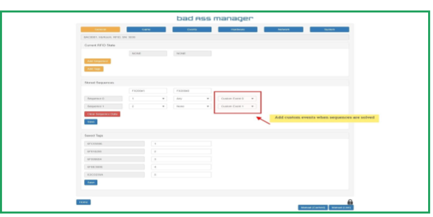
- Goto the Events page and under Reset Event remove #5 from the options box & save. When using this method of connecting the _Sprite _player, the output (ie output pin 5) CANNOT be addressed in any other location, it must be exclusive.

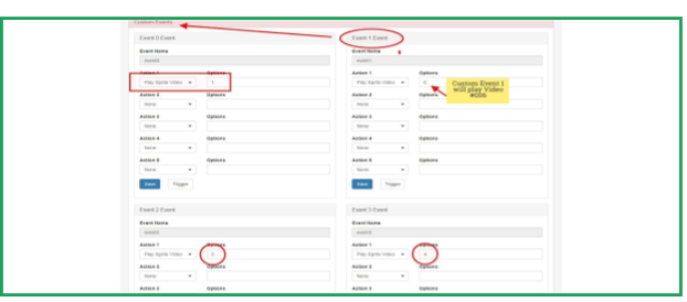
- From the Events page, press the Custom Events button/bar
- From the previous Game Learning page, select the matching custom event name (Custom Event 0)
- From the dropdown box In the Action 1 dropdown menu select “Play Sprite Video” and in the options box enter the number of the video to play. No leading zeros are required (ie video # 001 = 1)
- Sequence 0 when solved will trigger _ Custom Event 0_ playing video 1 on the Sprite
Sprite Serial Port Configuration
Hardware Connection Configuration

BAM Settings

- Goto the Hardware page, locate the Sprite Player section and check the “Enabled” box and from the dropdown box select the “Hardware Serial” option & save

- Goto the Events main screen and press the Input Events button/bar
- Select your Input Event and set your input trigger from the “Trigger On” dropdown box
- In the Action dropdown box, select the “Play Sprite Video” option
- In the Options box, enter the video # to play (no leading zeros are required ie 007 = 7)
- save
BAC Audio Addendum


Glossary of Terms
.Exe - Is a common filename extension denoting an executable file for Microsoft Windows
IP - An Internet Protocol address (IP address) is a numerical label assigned to each device connected to a computer network that uses the Internet Protocol for communication
MQTT - Communication protocol for small devices
I/O - (Input/Output)
BAM - Escape Room Techs Bad Ass Manager Web based user interface
RFID
RGB - Red Green Blue
RGBW - Red Green Blue White
M3
HMC
ERM
MS
SEC - Second
SPI - (Serial Peripheral Interface) - Interface to communicate between devices
EEprom - Programmable memory
SK6812
WS2812B
NeoPixel
MAC Address
DHCP
DNS Server
Heartbeat
UDP - (User Datagram Protocol) - Message exchange protocol
BAC - Escape Room Techs Bad ASS Controller
GM - Game Master
AC - Alternating current
DC - Direct current
VAC - Volts of AC power
VDC - Volts of DC power
A - Amperage, unit of current measurement. ex. 10 mA = 10 milliAmps or 0.01 Amps of current
Maglock
PSU
LED - (Light emitting diode) - Light source that emits light when current flows through it
NO/NC - Normally Open / Normally Closed
SW - Switch
Event Action
trigger(ed)
Half-Bridge Mode
Low Side / High Side
Technical Specs (Cut Sheet)
| BAC Voltage Requirements: DC Power ONLY | (10 – 24) VDC |
| Inputs (0-7) Maximum Voltage: | 24 VDC |
| Inputs (0-3):
Note: Approximately 100 pf of capacitance on inputs (0-3) |
“ON” Voltage: Greater than (~7.3 VDC)
“OFF” Voltage: Less than (~6.9 VDC) |
| Inputs (4-7): | “ON” Voltage: Greater than (~3.3 VDC)
“OFF” Voltage: Less than (~2.3 VDC) |
| Outputs (0-5) Maximum Current: | 500 mA maximum for each output channel
3000 mA (3 A) maximum cumulative output |
| ESD Protection: | 30KV HBM 2K pulldowns |
| BAC Current Draw:
Note: This is the idle state current draw. The current draw will increase depending on the implementation and what kind of external devices the BAC is powering. |
65 mA @24 VDC
120 mA @12 VDC 145 mA @10 VDC |
| Relay Outputs:
Maximum AC Voltage Switching Capability: *Caution - When using a relay to switch 120 VAC, proper enclosure is required, please consult Escape Room Techs first. Maximum DC Voltage Switching Capability: |
2 Relay Outputs (SPDT)
120 VAC, 10 A 30 VDC, 5 A |
| Memory: | Flash: 256KB
SRAM: 32KB EEPROM (user configuration): 256KB |
| Network: | 10/100BT Ethernet Support for Monitoring and Control |
| Expansion Capabilities:
Note: All expansion capabilities are available through the FX45 expansion board. |
Data Communication: Serial, I2C, HI-Drive I2C, Analog, RS485
Serial LED Driver (Configurable as 5 VDC or 12 VDC): Individually addressable LEDs; NeoPixels, WS2812B, SK6812 etc... |
| Processor: | Atmel ARM M0+ (ATSAMD21G18) |
| Mounting Options: | Enclosed Case, Din Rail or Board Holder |
| Dimensions: | PCB Length: 132mm (5-2/8")
PCB Width: 72mm (2-7/8") PCB Height (With Headers): 34mm ( 1-5/16”) Note: Connector J8 protrudes 9 mm past the right edge of the pcb which brings the total length of the device to 141mm (5-9/16”). Case Length: 153.5mm (6-1/16”) Case Width: 101.5mm (4”) Case Height: 38.5mm (1-9/16”) |