Many escape room operators use props from third-party manufacturers alongside Escape Room Techs equipment. This guide explains how to integrate these props with your BAC V controller for remote monitoring and override control from game master software like Escape Room Master, M3 or other systems.
Understanding the Challenge
Third-party props typically include their own control board that manages puzzle logic and controls an integrated magnetic lock. When guests solve the puzzle, the prop’s ‘brain’ releases the maglock.
The challenge is that these props operate as opaque boxes — the BAC can’t directly control the puzzle logic or see when they’re solved or control their locks without additional wiring.
This guide covers two approaches to integration, each with different tradeoffs.
Approach 1: Power Switching (Simpler Installation)
Best for: Operators who primarily need remote override capability and don’t need automated show control triggers based on puzzle completion.
In this approach, the BAC acts as a computer-controlled switch that cuts power to the entire prop, similar to a physical override switch. When you need to bypass a puzzle, you simply cut power to the prop, which – as part of turning off the entire prop – de-energizes its maglock and releases the lock.
Advantages
- Simple wiring — just interrupt the power line
- Can preserve existing physical override switches
- Works with any prop regardless of internal design
- Fastest installation time
Disadvantages
- No feedback to game software when puzzle is solved by guests
- Cannot trigger show control effects (lighting, sound, etc.) based on puzzle completion
- Cuts power to entire prop, not just the lock
What You’ll Need
For up to 2 props per BAC:
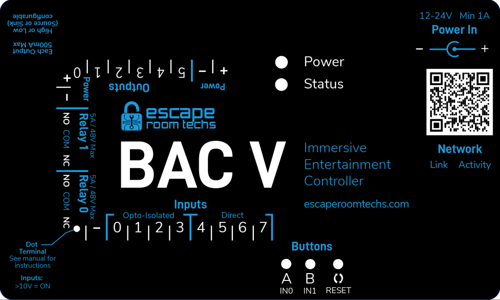
- Your BAC V controller (uses built-in relays)
- Appropriate-gauge wire for power connections
For 3-8 props per BAC:
- Your BAC V controller
- 8-Channel 12V Relay Module — one example is the HiLetgo 8 Channel 12V Relay Module (~$15)
- Appropriate-gauge wire for power and signal connections
Wiring Guide: Power Switching with External Relay Board
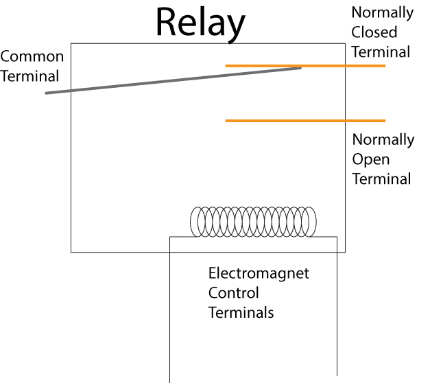
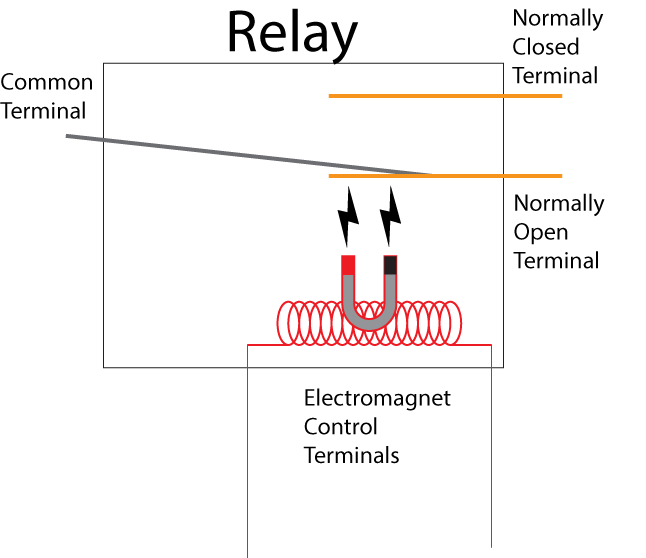
The relay board acts as 8 computer-controlled switches. Each relay has three terminals:
| Terminal | Function |
|---|---|
| COM (Common) | The shared connection point — wire your incoming power here |
| NC (Normally Closed) | Connected to COM when relay is OFF — prop receives power |
| NO (Normally Open) | Connected to COM when relay is ON — power is cut |
⚠️ SAFETY WARNING: Always disconnect power before making any wiring changes. Verify all connections before re-energizing. Incorrect wiring can damage equipment or create fire hazards.
Relay Board Configuration
The HiLetgo relay board has jumpers for selecting trigger level:
| Setting | When to Use |
|---|---|
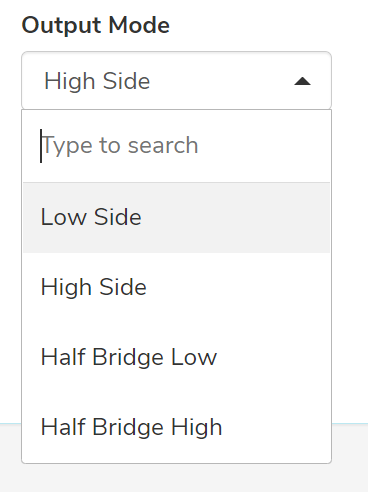
| HIGH | Use this setting with BAC V outputs set to “High side” (recommended) |
| LOW | Triggers the relay when the signal goes to ground, which is opposite how the BAC is typically configured unless “Low side” is selected. |
Important: Set the jumpers to HIGH level trigger before connecting to your BAC. The BAC V’s outputs go HIGH (+12V) when activated, which will then trigger the relay.
Step-by-Step Wiring
┌─────────────────────────────────────────────────────────────────────────────┐
│  POWER SWITCHING SETUP WITH 8-CHANNEL RELAY BOARD                           │
│                                                                             │
│  ┌─────────────────────────────┐                                            │
│  │ 12V POWER SUPPLY UNIT (PSU) │                                            │
│  │   +12V    GND               │                                            │
│  └────┬───────┬────────────────┘                                            │
│       │       │                                                             │
│       │       ├─────────────────────────────────────────────────────────┐   │
│       │       │                                                         │   │
│       │       │    ┌─────────────────────────────────────┐              │   │
│       │       │    │         BAC V CONTROLLER            │              │   │
│       │       │    │                                     │              │   │
│       │       │    │  Power Input: +12V ─────── GND      │              │   │
│       │       │    │               ↑             ↑       │              │   │
│       └───────┼────┼───────────────┼─────────────┘       │              │   │
│               │    │               │                     │              │   │
│               └────┼───────────────┘                     │              │   │
│                    │                                     │              │   │
│                    │  Output Header:                     │              │   │
│                    │  [+] [-] [0] [1] [2] [3] [4] [5]    │              │   │
│                    │   │   │   │   │   │   │   │   │     │              │   │
│                    └───┼───┼───┼───┼───┼───┼───┼───┼─────┘              │   │
│                        │   │   │   │   │   │   │   │                    │   │
│                        │   │   │   │   │   │   │   │                    │   │
│  ┌─────────────────────┼───┼───┼───┼───┼───┼───┼───┼────────────────┐   │   │
│  │  8-CHANNEL RELAY    │   │   │   │   │   │   │   │                │   │   │
│  │  MODULE             │   │   │   │   │   │   │   │                │   │   │
│  │                     │   │   │   │   │   │   │   │                │   │   │
│  │  Power: DC+ ────────┘   │   │   │   │   │   │   │                │   │   │
│  │         DC- ────────────┘   │   │   │   │   │   │                │   │   │
│  │                             │   │   │   │   │   │                │   │   │
│  │  Inputs: IN1 ───────────────┘   │   │   │   │   │                │   │   │
│  │          IN2 ───────────────────┘   │   │   │   │                │   │   │
│  │          IN3 ───────────────────────┘   │   │   │                │   │   │
│  │          IN4 ───────────────────────────┘   │   │                │   │   │
│  │          IN5 ───────────────────────────────┘   │                │   │   │
│  │          IN6 ───────────────────────────────────┘                │   │   │
│  │                                                                  │   │   │
│  │  (Note: IN7, IN8 can connect to BAC Relay 0 and Relay 1          │   │   │
│  │   COM terminals if you need all 8 channels active)               │   │   │
│  │                                                                  │   │   │
│  │  Relay Outputs (typically top of board):                         │   │   │
│  │  ┌─────┬─────┬─────┬─────┬─────┬─────┬─────┬─────┬─────┐...      │   │   │
│  │  │ NC1 │ COM1│ NO1 │ NC2 │ COM2│ NO2 │ NC3 │ COM3│ NO3 │         │   │   │
│  │  └──┬──┴──┬──┴─────┴──┬──┴──┬──┴─────┴──┬──┴──┬──┴─────┘         │   │   │
│  └─────┼─────┼───────────┼─────┼───────────┼─────┼──────────────────┘   │   │
│        │     │           │     │           │     │                      │   │
│        │     │           │     │           │     │                      │   │
│        │     └───────────)─────┼───────────)─────┼──────────────────────┘   │
│        │     │           │     │           │     │                          │
│        │  +12V from PSU  │  +12V from PSU  │  +12V from PSU                 │
│        │  goes to each   │                 │                                │
│        │  COM terminal   │                 │                                │
│        │                 │                 │                                │
│     ┌──┼──────────┐   ┌──┼──────────┐   ┌──┼──────────┐                     │
│     │  │PROP 1    │   │   PROP 2    │   │   PROP 3    │   ... etc.          │
│     │  │          │   │             │   │             │                     │
│     │ +12V ── GND │   │ +12V ── GND │   │ +12V ── GND │                     │
│     │         │   │   │         │   │   │         │   │                     │
│     │         │   │   │         │   │   │         │   │                     │
│     └─────── ─┼───┘   └─────────┼───┘   └─────────┼───┘                     │
│               │                 │                 │                         │
│               └─────────────────┴─────────────────┴─────── all to PSU GND   │
│                                                                             │
└───────────────────────────────────────────────────────────────────────────-─┘
Wiring Steps:
- Disconnect all power before beginning.
- Power the BAC: Connect +12V and GND from your power supply to the BAC’s barrel jack or terminal block.
- Power the relay board: Connect the BAC’s output header + terminal to the relay board’s DC+ terminal, and the BAC’s output header – terminal to the relay board’s DC- terminal.
- Connect trigger signals: Wire BAC Output 0 to relay board IN1, Output 1 to IN2, and so on through Output 5 to IN6.
- Wire +12V to relay COMs: Connect +12V from your power supply to each relay’s COM terminal. You can daisy-chain these connections.
- Wire props to relay NCs: Connect each relay’s NC (Normally Closed) terminal to the +12V input of its corresponding prop.
- Complete ground connections: Connect each prop’s GND terminal to the power supply’s GND.
- Double-check all connections before applying power.
Preserving Physical Override Switches
If you have existing physical override switches and want to keep them functional alongside the BAC control, wire them in series between the relay’s NC terminal and the prop’s +12V input:
PSU +12V → Relay COM → Relay NC → Physical Switch → Prop +12V InputThis way, either the BAC OR the physical switch can cut power to the prop.
Approach 2: Full Integration with Solve Detection (Advanced)
Best for: Operators who want automated show control (lighting changes, sound effects, etc.) triggered when guests solve puzzles, or who want to see real-time puzzle status in their game master software.
This approach uses two boards:
- An optocoupler board to safely read the prop’s maglock signal as a BAC input
- A relay board to independently control the maglock
The BAC sits “in the middle” — it monitors when the prop’s brain tries to release the lock (input), and it controls the actual lock release (output). This gives you full visibility and override capability.
Advantages
- See when each puzzle is solved in your game master software
- Trigger show control effects automatically when puzzles complete
- Full override capability independent of prop brain
- Can preserve automated unlock behavior while adding override
Disadvantages
- More complex wiring
- Requires intercepting maglock wiring inside each prop
- Higher parts cost
- More points of potential failure
What You’ll Need
- Your BAC V controller
- 8-Channel Optocoupler for reading prop signals on inputs; choose based on your power supply situation:
- If your props all share the same 12V power supply:
8-Channel Shared-Ground Optocoupler (~$12) - If your props have separate/independent power supplies:
1-Channel Individual Optocoupler Modules, 1 Per Input (~$10/6)
- If your props all share the same 12V power supply:
- 8-Channel 12V Relay Module for controlling outputs:
HiLetgo 8 Channel 12V Relay Module (~$15) - Appropriate-gauge wire for power and signal connections
Understanding Optocoupler Boards
Optocouplers provide electrical isolation between circuits. They use an internal LED and light sensor to transmit signals without any direct electrical connection. This is important because:
- It protects the BAC from voltage spikes or faults in the prop’s circuitry
- It prevents ground loops that can cause erratic behavior
- It allows connecting equipment with different power supplies safely
Shared-Ground Optocoupler (8-Channel Module)
This board has 10 pins on the input side:
| Pin | Connection |
|---|---|
| COM (×2) | Both connect to the negative side of your signal (prop’s GND when using NPN/active-low) |
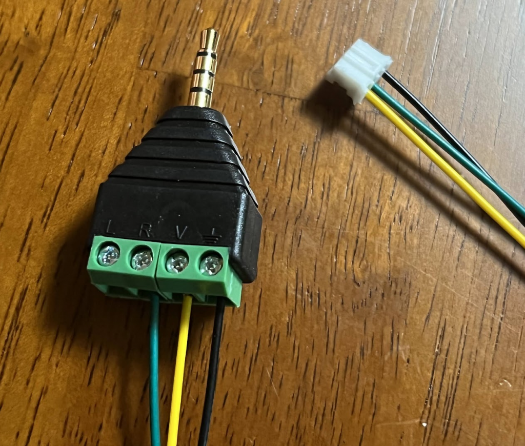
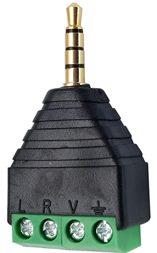
| X1-X8 | Connect to the positive signal from each prop’s maglock output |
⚠️ CRITICAL WARNING: The two COM terminals are internally connected. Connect them ONLY to positive OR negative — never both simultaneously, or you will short your power supply.
Output side (top to bottom): +12V power, – (GND), O1-O8 (outputs to BAC inputs)
When to use: All props share the same power supply, so they have a common ground reference.
Isolated Optocoupler (Individual Channel Type)
Each board has two independent input terminals, “IN+ and IN-“, which connect to the mag lock power from the prop.
| Pin | Connection |
|---|---|
| IN+ | Positive signal from prop |
| IN- | Negative/ground from prop |
The output side has three pins: VCC (for the BAC’s 12V power), OUT (output to BAC input), and GND (- terminal of BAC’s 12V power).
When to use: Props have different power supplies or you need complete isolation between channels.
How Prop Maglocks Typically Work
Most third-party prop maglocks are powered-to-lock (also called “fail-safe” or “fail-insecure”):
- When the maglock receives power, it stays locked
- When power is cut, the lock releases
The prop’s brain controls a small relay or transistor that switches power to the maglock. When guests solve the puzzle, the brain cuts power to the lock.
To intercept this signal:
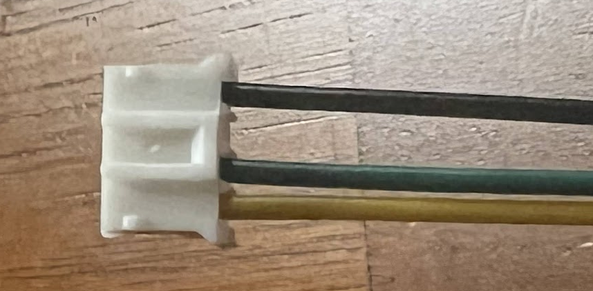
- Locate the wires going from the prop’s control board to its maglock
- These are typically two wires: +12V (switched) and GND
- The +12V wire will show voltage when locked, no voltage when unlocked
Wiring Guide: Full Integration
┌─────────────────────────────────────────────────────────────────────────────┐
│  FULL INTEGRATION: SOLVE DETECTION + OVERRIDE CONTROL                       │
│                                                                             │
│  Inside each third-party prop:                                              │
│                                                                             │
│  ┌────────────────────────────────────────────────────────┐                 │
│  │  PROP INTERNAL WIRING (you will modify this)           │                 │
│  │                                                        │                 │
│  │  ┌──────────┐      Original wiring    ┌──────────┐     │                 │
│  │  │  PROP    │  +12V (switched) ──X──► │ MAGLOCK  │     │                 │
│  │  │  BRAIN   │  GND ──────────────X──► │          │     │                 │
│  │  └──────────┘       (disconnect)      └──────────┘     │                 │
│  │                                                        │                 │
│  │  New wiring:                                           │                 │
│  │  ┌──────────┐                                          │                 │
│  │  │  PROP    │  +12V (switched) ──────► To Optocoupler  │                 │
│  │  │  BRAIN   │  GND ──────────────────► To Optocoupler  │                 │
│  │  └──────────┘                          (reads solve)   │                 │
│  │                                                        │                 │
│  │  ┌──────────┐                                          │                 │
│  │  │ MAGLOCK  │  +12V ◄─────────────── From Relay Board  │                 │
│  │  │          │  GND ◄──────────────── From PSU GND      │                 │
│  │  └──────────┘                         (BAC controlled) │                 │
│  └────────────────────────────────────────────────────────┘                 │
│                                                                             │
│                                                                             │
│  ┌──────────────────────────────────────────────────────────────────────┐   │
│  │  CENTRAL CONTROL PANEL                                               │   │
│  │                                                                      │   │
│  │  ┌─────────────────────┐         ┌─────────────────────────┐         │   │
│  │  │ SHARED-GROUND       │         │ BAC V CONTROLLER        │         │   │
│  │  │ OPTOCOUPLER         │         │                         │         │   │
│  │  │                     │         │ Inputs: 0 1 2 3 4 5 6 7 │         │   │
│  │  │ Inputs:             │         │         ↑ ↑ ↑ ↑ ↑ ↑ ↑ ↑ │         │   │
│  │  │ COM ── to PSU GND   │         │         │ │ │ │ │ │ │ │ │         │   │
│  │  │ COM ── to PSU GND   │ Outputs │         │ │ │ │ │ │ │ │ │         │   │
│  │  │ X1 ◄── Prop 1 +12V  │ O1-O8 ──┼────────►┘ │ │ │ │ │ │ │ │         │   │
│  │  │ X2 ◄── Prop 2 +12V  │ go to   │                         │         │   │
│  │  │ X3 ◄── Prop 3 +12V  │ BAC     │                         │         │   │
│  │  │ ...                 │ inputs  │                         │         │   │
│  │  │ X8 ◄── Prop 8 +12V  │         │                         │         │   │
│  │  │                     │         │                         │         │   │
│  │  │ Power:              │         │                         │         │   │
│  │  │ + ◄── 12V from PSU  │         │ Outputs: 0 1 2 3 4 5    │         │   │
│  │  │ - ◄── GND from PSU  │         │          │ │ │ │ │ │    │         │   │
│  │  └─────────────────────┘         └──────────┼─┼─┼─┼─┼─┼────┘         │   │
│  │                                             │ │ │ │ │ │              │   │
│  │                                             ▼ ▼ ▼ ▼ ▼ ▼              │   │
│  │  ┌────────────────────────────────────────────────────────────────┐  │   │
│  │  │ 8-CHANNEL RELAY MODULE                                         │  │   │
│  │  │                                                                │  │   │
│  │  │ Power: DC+ ◄── from BAC output header +                        │  │   │
│  │  │        DC- ◄── from BAC output header -                        │  │   │
│  │  │                                                                │  │   │
│  │  │ Inputs: IN1 IN2 IN3 IN4 IN5 IN6 IN7 IN8                        │  │   │
│  │  │          ↑   ↑   ↑   ↑   ↑   ↑   ↑   ↑                         │  │   │
│  │  │         From BAC outputs 0-5 and relays                        │  │   │
│  │  │                                                                │  │   │
│  │  │ Relay Outputs:                                                 │  │   │
│  │  │ NC1┐    COM1┐  NO1┐       NC2┐    COM2┐  NO1┐   ...            │  │   │
│  │  │    │        │     x          │        │     x   ...            │  │   │
│  │  │  Prop 1   +12V             Prop 2   +12V        ...            │  │   │
|  |  |  Lock +                    Lock +               ...            │  │   │
│  │  │                                                                │  │   │
│  │  │                                                                │  │   │
│  │  └─────┼────────────────────────┼─────────────────────────────────┘  │   │
│  │        │                        │                                    │   │
│  │        ▼                        ▼                                    │   │
│  │        +   - ◄── GND from PSU   +   - ◄── GND from PSU               │   │
│  │      Prop 1                   Prop 2                                 │   │
│  │      Maglock                  Maglock                                │   │
│  │                                                                      │   │
│  └──────────────────────────────────────────────────────────────────────┘   │
│                                                                             │
└─────────────────────────────────────────────────────────────────────────────┘
Step-by-Step Wiring:
- Disconnect all power and verify no voltage is present.
- Modify each prop internally:
- Locate the wires from the prop brain to its maglock
- Disconnect the maglock from the prop brain
- Route the prop brain’s maglock output wires to your central control panel (these go to the optocoupler inputs)
- Route new wires from the relay board back to the maglock
- Set up the optocoupler board:
- Connect the COM terminal(s) to the – terminal of the prop power supply
- Connect the input(s) to the +12V switched lock output(s) from each prop brain
- Power the board on the output side from the BAC, + to 12V, – to GND
- Connect the output(s) to BAC inputs 0-7
- Set up the relay board:
- Set jumpers to HIGH level trigger
- Connect DC+ and DC- to BAC output header + and –
- Connect IN1-IN6 to BAC outputs 0-5
- Connect IN7-IN8 to the NO terminals of BAC Relay 0 and Relay 1 if you need all 8 channels (and then wire a jumper wire from COM to the BAC’s +12V to complete the circuit)
- Wire the relay outputs to maglocks:
- Connect +12V from PSU to each relay’s COM terminal
- Connect each relay’s NC terminal to its corresponding maglock’s +12V input
- Connect all maglock GND terminals to PSU GND
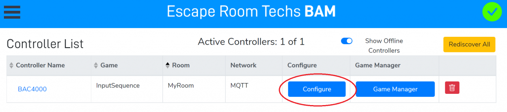
- Configure the BAC in BAM:
- Set inputs to trigger on appropriate level (typically LOW when optocoupler activates)
- Set up events to echo inputs to outputs for automatic unlock behavior
- Configure game control software integration for more advanced control
Programming the BAC for Auto-Unlock with Override
To make the BAC automatically release the lock when the prop is solved, while still allowing manual override:
- Open BAM and navigate to Events → Input Events
- For each input (e.g., Input 0):
- Set “Trigger On” to match when the prop signals solved (test with your specific optocoupler)
- Add action: “Turn Off Output 0” (or “Turn On Relay 0” depending on your wiring)
- This creates automatic pass-through behavior
- GMs can still manually trigger outputs/relays for override
Channel Limitations and Solutions
The BAC V provides:
- 8 inputs (0-7)
- 6 outputs (0-5)
- 2 relays (0-1)
Maximum channels per BAC: 8 (using all outputs and relays for control)
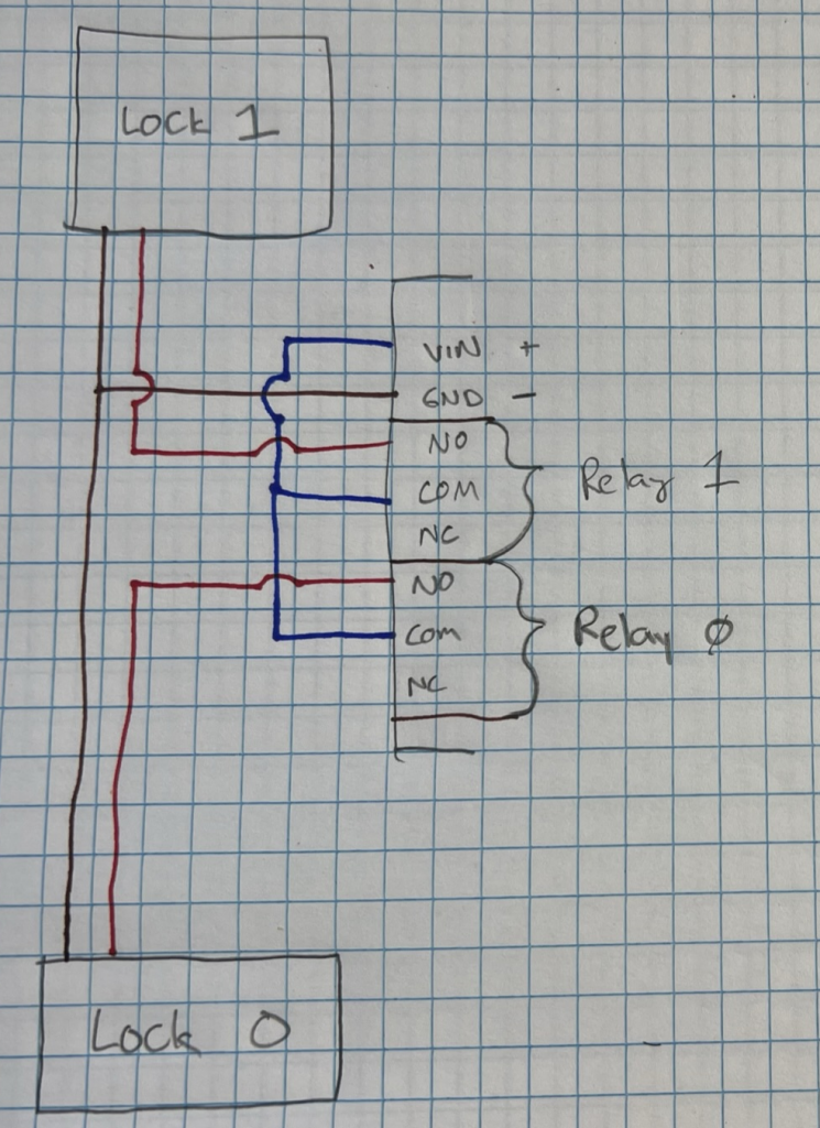
Using the BAC Relays as Outputs
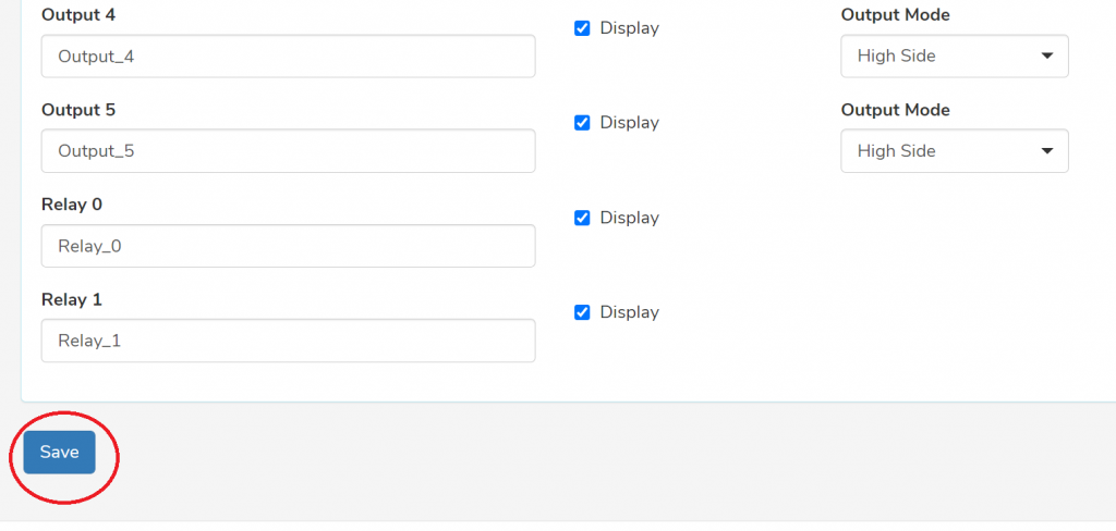
If you need 7 or 8 channels of control, you can use the BAC’s two onboard relays as additional outputs instead of just the 6 digital outputs.
Wire +12V from your power supply (or from the + terminal on the BAC’s output header) to the relay’s COM terminal, then connect the relay’s NO (Normally Open) terminal to your load — whether that’s a maglock directly or an input on an external relay board.
When you activate the relay via software, COM connects to NO and your load receives power, just like turning on a digital output. This gives you a full 8 channels: outputs 0-5 driving IN1-IN6 on your relay board, and the two onboard relays driving IN7-IN8.
If You Have More Than 8 Props
| Solution | Description |
|---|---|
| Multiple BACs | Use two or more BAC V controllers, each handling up to 8 props |
| Keep some manual | Designate 1-2 props as manual-only with physical switches |
| Group props | Wire multiple props to single channel if they’re always overridden together |
Troubleshooting
Relay doesn’t switch when BAC output activates
- Verify relay board jumpers are set to HIGH level trigger
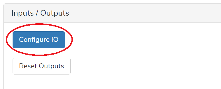
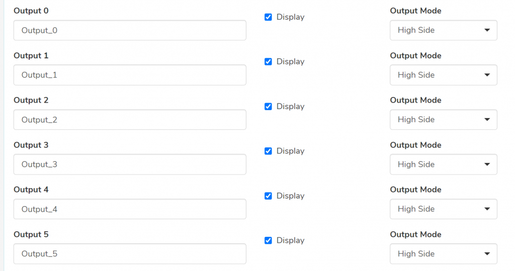
- Check BAC output mode in BAM → Hardware → Configure IO (should be High Side for most relay boards)
- Verify DC+ and DC- connections from BAC to relay board
Optocoupler doesn’t detect prop solve signal
- Verify prop brain is actually outputting voltage when locked (measure with multimeter)
- Check COM connections on optocoupler (should go to same reference as prop brain GND)
- Verify optocoupler output voltage matches BAC input requirements
Prop doesn’t unlock when relay activates
- Verify you’re using NC (Normally Closed) terminal, not NO
- Check that +12V is connected to COM terminal
- Verify maglock polarity and connections
Erratic behavior or random triggering
- Check for ground loops — all equipment should share common ground reference
- Add flyback diodes across maglock terminals if not already present
- Verify adequate power supply capacity
Safety Reminders
⚠️ Always disconnect power before making wiring changes.
⚠️ Verify all connections with a multimeter before applying power.
⚠️ Use appropriate wire gauges for your lock’s current draw.
⚠️ Never connect optocoupler COM terminals to both positive AND negative simultaneously.
⚠️ Ensure adequate power supply capacity — maglocks can draw 200-650mA each; calculate total load and validate your power supply before adding props.
⚠️ Consider fire safety — secure all wiring, use appropriate enclosures, and follow local electrical codes.
Additional Resources
- What is a relay? How is it different from a digital output?
- How do I change my BAC V’s outputs between High Side or Low Side?
- BAC/BAM Manual
- Master Command Table (for network control)
Need Help?
Integration projects can be complex! We’re happy to assist:
- Email: escape@escaperoomtechs.com
- Facebook Messenger: m.me/escaperoomtechs (fastest response)
Please note that while we’re always happy to help with BAC setup and configuration, a consulting fee may apply for custom engineering or extensive troubleshooting of third-party equipment we didn’t manufacture.